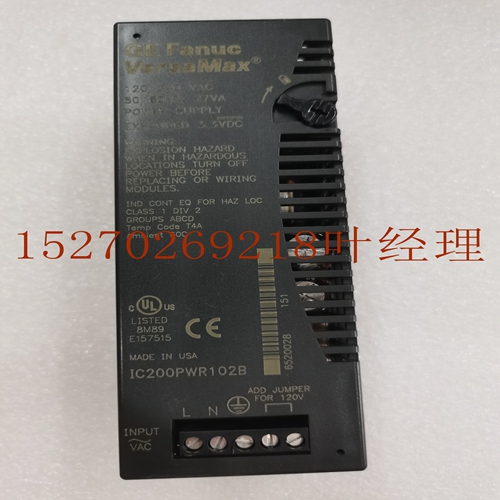
IS200JPDSG1ACB控制模块,工控模块卡件
负载二极管GFK-1504N第2章安装2-21 2紧凑型载体(IC200CHS022、IC200CHS025)现场接线端子紧凑型载体上的每个端子容纳一根实心或绞合AWG#14(平均横截面2.1mm2)至AWG#22(平均横截面积0.36mm2)导线,或两根AWG#18(平均横面积0.86mm2)导线。使用额定温度为90摄氏度的铜线。在同一位置插入两根电线时,电线的尺寸和类型必须相同(实心或绞合)。载波可以适应每个点2安培或每个电源和接地8安培的电流水平,电压范围高达264伏交流电。高达300伏交流电的电压瞬变不会损坏载波。对于箱式托架,建议的终端扭矩为0.37至0.45 ft-lbs。与模块一起提供的标签可以折叠并插入标签夹持器中。盒式或弹簧式紧凑型托架A1 A2 A3 A4 A5 A6 B1 B2 B3 B4 B5 B6 A7 A8 A9 A10 A11 A12 B7 B8 B9 B10 B12 A13 A14 A15 A16 A18 B13 B14 B15 B16 B17 B18 B11 2-22 VersaMax模块的端子编号,电源和托架用户手册GFK-1504N 2盒型托架或弹簧型托架(IC200CHS002、IC200CHS005)的接线B a H G F 8 2 6 4 B C 7 D 3现场接线端子盒型或弹簧型载体上的每个端子容纳一根实心或绞合AWG#14(平均横截面2.1mm2)至AWG#22(平均横截面积0.36mm2)导线,或两条AWG#18电线(平均横截面0.86mm2)。使用额定温度为90摄氏度的铜线。在同一位置插入两根电线时,电线的尺寸和类型必须相同(实心或绞合)。载波可以适应每个点2安培或每个电源和接地8安培的电流水平,电压范围高达264伏交流电。高达300伏交流电的电压瞬变不会损坏载波。对于箱式托架,建议的终端扭矩为0.37至0.45 ft-lbs。随模块提供的标签可以折叠并插入模块的透明门中。盒式或弹簧式托架A1 A2 A3 A4 A5 A6 A7 A8 A9 A10 A11 A12 A13 A14 A15 A16 A17 A18 B1 B2 B3 B4 B5 B6 B7 B8 B9 B10 B11 B12 B13 B14 B15 B16 B17 B18 GFK-1504N第2章安装屏障式托架上的每个端子容纳一根或两根从AWG#22(平均横截面0.36mm2)到AWG#14(平均横截面积2.1mm2)的实心或绞合导线。使用额定温度为90摄氏度的铜线。在同一位置插入两根电线时,电线的尺寸和类型必须相同(实心或绞合)。载波可以适应每个点2安培或每个电源和接地8安培的电流水平,电压范围高达264伏交流电。高达300伏交流电的电压瞬变不会损坏载波。对于屏障式托架,建议的终端扭矩为0.37至0.50 ft-lbs。随模块提供的标签可以折叠并插入模块的透明门中。隔离栅型载体VersaMax模块、电源和载体的端子编号用户手册GFK-1504N 2连接器型载体接线(IC200CHS003)连接器型载体现场连接通常与插入式端子单元和一个或多个辅助端子连接。然而,也可以使用压接到现场导线端部的触点将现场导线直接连接到ConnectorStyle载体本身。
Load Diode GFK-1504N Chapter 2 Installation 2-21 2 Wiring for a Compact Carrier (IC200CHS022, IC200CHS025) Field Wiring Terminals Each terminal on a Compact-style Carrier accommodates one solid or stranded AWG #14 (avg. 2.1mm2 cross section) to AWG #22 (avg. 0.36mm2 cross section) wire, or two wires up to AWG #18 (avg. 0.86mm2 cross section). Use copper wire rated for 90 degrees C. When inserting two wires in the same position, the wires must be the same size and type (solid or stranded). The carrier can accommodate current levels up to 2 Amps per point or 8 Amps per each power and ground, and a voltage range of up to 264 V AC. Voltage transients up to 300 V AC will not damage the carrier. For a Box-Style Carrier, recommended terminal torque is 0.37 to 0.45 ft-lbs. The label provided with the module can be folded and inserted in the label holder. Terminal Numbering for a Box- or Spring-Style Compact Carrier A1 A2 A3 A4 A5 A6 B1 B2 B3 B4 B5 B6 A7 A8 A9 A10 A11 A12 B7 B8 B9 B10 B12 A13 A14 A15 A16 A17 A18 B13 B14 B15 B16 B17 B18 B11 2-22 VersaMax Modules, Power Supplies and CarriersUser Manual GFK-1504N 2 Wiring for a Box-Style Carrier or Spring-Style Carrier (IC200CHS002, IC200CHS005) B A H G F 8 2 6 4 B C 7 D 3 Field Wiring Terminals Each terminal on a Box-Style or Spring-Style Carrier accommodates one solid or stranded AWG #14 (avg. 2.1mm2 cross section) to AWG #22 (avg. 0.36mm2 cross section) wire, or two wires up to AWG #18 (avg. 0.86mm2 cross section). Use copper wire rated for 90 degrees C. When inserting two wires in the same position, the wires must be the same size and type (solid or stranded). The carrier can accommodate current levels up to 2 Amps per point or 8 Amps per each power and ground, and a voltage range of up to 264 V AC. Voltage transients up to 300 V AC will not damage the carrier. For a Box-Style Carrier, recommended terminal torque is 0.37 to 0.45 ft-lbs. The label provided with the module can be folded and inserted in the module’s transparent door. Terminal Numbering for a Box-Style or Spring-Style Carrier A1 A2 A3 A4 A5 A6 A7 A8 A9 A10 A11 A12 A13 A14 A15 A16 A17 A18 B1 B2 B3 B4 B5 B6 B7 B8 B9 B10 B11 B12 B13 B14 B15 B16 B17 B18 GFK-1504N Chapter 2 Installation Each terminal on a Barrier-Style Carrier accommodates one or two solid or stranded wires from AWG #22 (avg. 0.36mm2 cross section) to AWG #14 (avg. 2.1mm2 cross section). Use copper wire rated for 90 degrees C. When inserting two wires in the same position, the wires must be the same size and type (solid or stranded). The carrier can accommodate current levels up to 2 Amps per point or 8 Amps per each power and ground, and a voltage range of up to 264 V AC. Voltage transients up to 300 V AC will not damage the carrier. For a Barrier-Style Carrier, recommended terminal torque is 0.37 to 0.50 ft-lbs. The label provided with the module can be folded and inserted in the module’s transparent door. Terminal Numbering for a Barrier-Style Carrier VersaMax Modules, Power Supplies and CarriersUser Manual GFK-1504N 2 Wiring for a Connector-Style Carrier (IC200CHS003) For a Connector-Style Carrier field connections are usually made to an Interposing Terminal unit and one or more Auxiliary Terminals. However, it is also possible to make field wiring connections directly to the ConnectorStyle Carrier itself using contacts crimped to the ends of the field wires.


