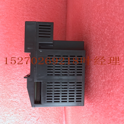
IS200NATCH1CPR3通用电气卡件,工控卡件
. MOV的大小应能处理线路瞬变。用于处理正常线路瞬变的合适MOV示例包括Littelfuse制造的以下产品:V36ZA80(非隔离24 V DC V130LA20AP(120 V AC应用)V275LA40BP(240 V AC应用程序)在极端情况下,可能需要测量实际瞬变,以确定最佳MOV。在电源上安装抑制装置下图显示了典型的电源和接地连接。+/-DC:+或AC:H DC:-或AC:N 2-18 VersaMax模块、电源和托架用户手册GFK-1504N 2机柜中设备的安装抑制对于机柜中安装的一组设备,MOV可以安装在电源线进入机柜的位置。理想情况下,应在系统中的每个机柜处使用MOV,以实现最大保护。下图说明了电源线和进入机柜的通信总线的抑制。模块外壳电源短长度通信总线电缆定期检查和更换MOV MOV可以很好地吸收通信、控制和电源线上的瞬变,前提是这些瞬变的总能量不超过设备的额定值。然而,如果瞬态能量超过设备额定值,MOV可能损坏或损坏。该故障可能不明显或不明显。应定期检查MOV是否有损坏迹象,以确保对瞬态的持续保护。对于某些应用,建议定期更换关键MOV,即使它们没有显示损坏迹象。GFK-1504N第2章安装2-19 2系统接地控制系统的所有部件及其控制的设备必须正确接地。接地导体应以星形方式连接,所有分支均应布线至中心接地点。这确保了没有接地导体从任何其他分支输送电流。编程设备每个接线板电机驱动器和其他电气控制设备机械接地中心接地点信号和电源连接未显示控制面板和外壳也应根据代码连接至工厂系统接地。在出现电源开关瞬态和浪涌时,接地不足可能会损害系统的完整性。2-20 VersaMax模块、电源和托架用户手册GFK-1504N 2安装感应负载设备接线当将输出接线至感应负载时,建议使用外部抑制电路。如果可能,外部抑制电路应跨接在实际负载上。如果不可能,则应将外部抑制电路连接到将驱动感应负载的每个点。交流感应负载对于交流感应负载,缓冲网络应由250 V交流、0.1µF电容器组成,电容器与100欧姆½瓦或更高的电阻器串联。可根据应用选择具有不同工作电压的电容器。推荐的缓冲器组件包括Paktron的104M06QC100或104M06RL100。直流感应负载对于直流感应负载,应在负载两端放置二极管,如下所示。推荐的二极管包括:1N4934 100 V,1A;1N4936 400伏,1A;1N4937 600伏,1A。这些二极管可从大多数制造商处获得。隔离输出,隔离输出点隔离输出点电感负载100欧姆½瓦0.1µF 250VAC隔离输出的AC回路,隔离输出端隔离输出点感应负载二极管组输出的DC回路,AC A18和/或B18输出点电感输出100欧姆½瓦特0.1µF 250 VAC组输出,DC A18和或B18输入点电感
The MOV should be sized to handle line transients. Examples of suitable MOVs to handle normal line transients include the following products manufactured by Littelfuse: V36ZA80 (Non-isolated 24 V DC V130LA20AP (120 V AC applications) V275LA40BP (240 V AC applications) Measurement of actual transients may be required in extreme cases to decide what MOV is best. Installing Suppression at the Power Supply The following figure displays typical power and ground connections. + - DC: + or AC: H DC: - or AC: N 2-18 VersaMax Modules, Power Supplies and CarriersUser Manual GFK-1504N 2 Installing Suppression for Devices in an Enclosure For a group of devices installed in an enclosure, MOVs can be installed at the point where the power lines enter the enclosure. Ideally, MOVs should be used at each cabinet in the system for maximum protection. The following figure illustrates suppression on both power lines and a communications bus entering an enclosure. Enclosure Power to Modules Short Length of Communications Bus Cable Periodic Inspection and Replacement of MOVs MOVs do a good job of absorbing transients on communications, control, and power lines, provided the total energy of those transients does not exceed the rating of the device. However, if the energy of the transient exceeds the rating of the device, the MOV may be either damaged or destroyed. This failure may not be visibly or electrically evident. MOVs should be regularly inspected for signs of damage to assure continued protection against transients. For some applications, periodic replacement of critical MOVs is recommended, even if they do not show signs of damage. GFK-1504N Chapter 2 Installation 2-19 2 System Grounding All components of a control system and the devices it controls must be properly grounded. Ground conductors should be connected in a star fashion, with all branches routed to a central earth ground point. This ensures that no ground conductor carries current from any other branch. Programming Device Each Terminal Block Motor Drives and Other Electrical Control Equipment Machinery Earth Ground Central Ground Point Signal and power connections not shown The control panel and enclosure should also be bonded to the plant system ground per code. Inadequate grounding may compromise system integrity in the presence of power switching transients and surges. 2-20 VersaMax Modules, Power Supplies and CarriersUser Manual GFK-1504N 2 Installing Wiring for Devices Wiring to Inductive Loads When wiring outputs to inductive loads, use of external suppression circuits is recommended. If possible, the external suppression circuits should be connected across the actual load. If that is not possible, external suppression circuits should be connected to each point that will drive an inductive load. AC Inductive Loads For AC inductive loads, the snubber network should consist of a 250 V AC, 0.1µF capacitor connected in series with a 100 Ohm ½ Watt or higher resistor. A capacitor with a different working voltage may be chosen, as appropriate for the application. Recommended snubber packages include 104M06QC100 or 104M06RL100 from Paktron. DC Inductive Loads For DC inductive loads, a diode should be placed across the load as shown below. Recommended diodes include: 1N4934 100 V, 1A; 1N4936 400 V, 1A; 1N4937 600 V, 1A. These diodes are available from most manufacturers. Isolated Outputs, AC Return for Isolated Output Point Isolated Output Point Inductive Load 100 Ohm ½ Watt 0.1µF 250VAC Isolated Outputs, DC Return for Isolated Output Point Isolated Output Point Inductive Load Diode Grouped Outputs, AC A18 and/or B18 Output Point Inductive Load 100 Ohm ½ Watt 0.1µF 250VAC Grouped Outputs, DC A18 and/or B18 Output Point Inductive


