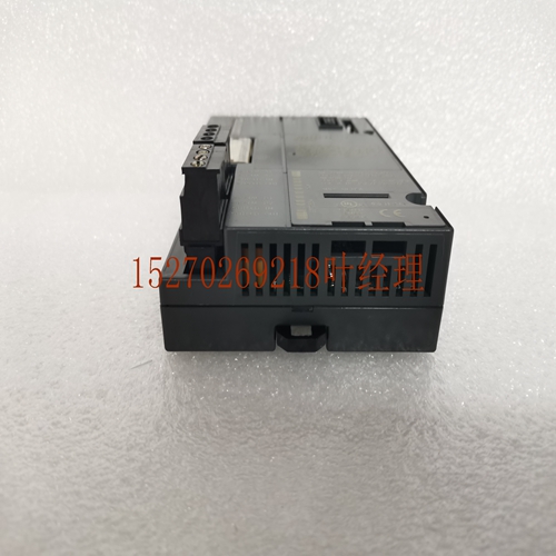
IS200STCIH2AED通用电气卡件
两个表均可通过Logicmaster 90软件、CIMPLICITY Intouch操作员界面软件和访问显示系统获得,无需额外编程。检测到故障或系统状态变化后,相应的故障表中将显示位置、描述和时间。按下功能键可显示有关故障的其他描述性信息。选项允许永久记录打印日志。典型PLC故障表显示故障和无故障触点为了将特定的诊断动作集成到应用程序中,离散或模拟故障和非GMR配置的模拟报警位可以与表决或物理输入以及单工和容错输出相关联。以下示例显示了与特定机架和电路相关的故障触点,以及与特定插槽相关的无故障触点。示例故障触点RACK_01 SLOT_15%I1033%Q00002-[FULT]-[NOFLT] 当故障表中清除故障时,重置故障位。GMR程序保护为了确保完整性,GMR系统为应用程序提供可选的硬件和软件保护级别。整个程序和GMR软件可以使用每个CPU模块顶部的钥匙开关进行硬件锁定。CPU上的LED提供钥匙开关锁定的视觉确认。为了获得额外的保护,可以使用一系列四个权限级别来限制对特定软件功能的访问。每个级别可以分配一个唯一的密码。下面所示的示例适用于TÜV TMR系统:访问级别软件安全访问描述4更改密码、写入或修改程序逻辑和/或配置3写入或修改编程逻辑和//或配置,2写入数据存储器,即更改计时器和计数器值、预设值等。。。1仅读取PLC数据,密码除外。无PLC内存更改。保护甚至扩展到应用程序中的各个程序块,这些程序块可以被锁定和密码。这种灵活的程序保护方案允许授权用户访问程序的非关键部分,同时防止进入不可更改的逻辑区域。系统扫描时间估计的扫描时间取决于PLC系统、系统、程序复杂性和其他几个因素。附录B给出了有关估计扫描时间的信息。嵌入式协议通信多种通信协议、媒体和连接类型可用于连接到各种智能设备。5-8 Genius®模块冗余灵活三模块冗余(TMR)GFT-177A系统技术产品概述–1998年2月5自动程序文档Logicmaster 90包括生成有关GMR应用程序的多种类型文档的能力。Logicmaster打印菜单用于指定打印输出的内容和格式。Logicmaster Print Menu(Logicmaster打印菜单)从该菜单中选择项目可定制打印输出,以包括整个GMR程序或程序选定部分的配置数据、程序逻辑、交叉引用、变量和程序注释。以下示例显示了Logicmaster软件中机架配置打印输出和单个模块配置打印输出的部分。使用GMR软件进行的配置也会打印出来(此处未显示)。部分配置打印输出部分程序逻辑打印输出GFT-177A第5节配置和编程GMR系统5-9 5在线编程和存储
Both tables can be obtained through Logicmaster 90 software, CIMPLICITY Intouch operator interface software and access display system without additional programming. After a fault or system status change is detected, the corresponding fault table will display the location, description and time. Press the function key to display additional descriptive information about the fault. The option allows a print log to be recorded permanently. Typical PLC fault tables show fault and fault free contacts In order to integrate specific diagnostic actions into the application, discrete or analog faults and analog alarm bits for non GMR configurations can be associated with voting or physical inputs and simplex and fault-tolerant outputs. The following examples show the fault contacts associated with a particular frame and circuit, and the fault free contacts associated with a particular slot. Example fault contact RACK_ 01 SLOT_ 15% I1033% Q00,002 - [FULT] - [NOFLT] When the fault is cleared in the fault table, reset the fault bit. GMR Program Protection To ensure integrity, the GMR system provides optional hardware and software protection levels for applications. The entire program and GMR software can be hardware locked using the key switch on the top of each CPU module. LEDs on the CPU provide visual confirmation of key switch locking. For additional protection, a series of four permission levels can be used to restrict access to specific software functions. Each level can be assigned a unique password. The example shown below is applicable to T | V TMR system: access level software security access description 4 Change password, write or modify program logic and/or configuration 3 Write or modify programming logic and/or configuration, 2 Write to data memory, that is, change timer and counter values, preset values, etc... 1 Read PLC data only, except passwords. No PLC memory changes. The protection even extends to the various program blocks in the application, which can be locked and encrypted. This flexible program protection scheme allows authorized users to access non critical parts of the program while preventing them from entering unchangeable logical areas. System scan time The estimated scan time depends on the PLC system, system, program complexity, and several other factors. Appendix B provides information on estimated scan times. Embedded protocol communication A variety of communication protocols, media, and connection types can be used to connect to various intelligent devices. 5-8 Genius ® Module Redundancy Flexible Three Module Redundancy (TMR) GFT-177A System Technology Product Overview – February 5, 1998 Automatic program documentation Logicmaster 90 includes the ability to generate multiple types of documentation about GMR applications. The Logicmaster Print menu is used to specify the content and format of the printout. Logicmaster Print Menu Select an item from this menu to customize the printout to include configuration data, program logic, cross references, variables, and program notes for the entire GMR program or a selected part of the program. The following examples show the rack configuration printouts and the individual module configuration printouts in Logicmaster software. The configuration using GMR software will also be printed (not shown here). Partial configuration Printout partial program logic Printout GFT-177A Section 5 Configuration and programming GMR system 5-9 5 Online programming and storage


