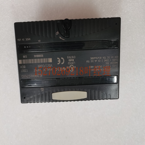
IS200STTCH2A工业自动化卡件
T模块2的端子模块1的端子DIN导轨闩锁键槽电缆连接器面板安装脚DIN导轨闩锁键槽电缆接头面板安装脚现场控制接线板接线板有两套独立的模块端子。每组对应于常规机架式PLC中的一个“插槽”。电缆连接器便于连接传输通信信号的电缆。DIN导轨闩锁将接线板夹在DIN导轨上。键槽允许保护模块键控。端子样式端子块可用于下图所示的端子样式。不同的接线板类型可以在一个站内混合使用。46418接线盒端子安全栅端子接线板连接器带安全栅端子的接线板(产品目录号IC670CHS101)有37个端子。每个端子可容纳一条或两条AWG#14(平均横截面2.1mm 2)的电线。带接线盒端子的接线盒(目录号IC670CHS102)有51个端子,每个端子可容纳一个AWG#14(平均2.1mm 2横截面)至AWG#22导线(平均0.36mm 2横截面积),或两个AWG#18(平均0.86mm 2横截)的导线。可使用绝缘外部5mm(0.2in)跳线(如Altech#8879)连接相邻的。使用外部跳线时,导线容量从AWG#14(2.10mm 2)减少到AWG#16(1.32mm 2)。带接头的接线板(目录号IC670CHS103)有两个20针公接头用于接线。配合接头为Amp零件号178289-8。连接器带有键,以防止错误插入。AMP D–3000系列中的任何镀锡触点都可以与连接器一起使用(AMP零件号1-175217-5用于20-24规格(0.20–0.56mm2)电线的高接触力插座,1-175218-5用于16-20规格(0.56-1.42mm2)的高接触压力插座)。GE Fanuc零件号C670ACC003提供了包含两个配合连接器外壳和触点的套件。GFT-177A第4节产品规范4-33 4现场控制模块规范下面列出的总线接口单元现场控制模拟输入模块和接线板可能属于GMR输入组。TMR模拟输入由一组最多三个具有相同类型模块的现场控制站提供。在所有GMR CPU处接收重复和重复的输入数据,然后在执行应用程序之前进行表决,以确保所使用的输入数据的最高完整性。对三重数据的投票是中间值选择,在失败的情况下,投票适应平均值,选择高或选择低。第二次失败导致进一步的表决自适应,以使用最后的操作输入或进入预先配置的最小值、最大值或保持最后的状态值。BIU、模块或电路故障会导致相应的诊断LED指示和故障记录到每个PLC的故障表中。TMR模拟输入继续与输入组的其余“支路”一起工作。现场控制模拟输入模块总线接口单元接线板目录热敏电阻错误--GFT-177A 5-1本节的目的是解释GMR系统软件设置和编程的基础知识。下图概述了三个GMR 788/798或790 PLC的配置和编程。特殊GMR软件和Logicmaster 90-70软件都有助于系统配置和完成的应用程序。系统中的Genius块和现场控制BIU是独立配置的。CONFIG.EXE GMRxxyy KEY0.DEF GMR配置GMR配置打印输出LM90配置CONFIGA CONFIGB LM90编程应用程序LM90复制文件夹CONFIGC GMR磁盘LM90复制文件LM90复制存储LM90存储LM90未来程序更新使用手持监视器阻止配置G_M_R_程序文件夹790嵌入配置。数据G_M_R10程序块LM90库管理员788/789 PLC A PLC B PLC C基本GMR系统配置和编程步骤5 GMR系统的配置和编程第T M R G M RTM 5-2节Genius®模块化冗余灵活三模块冗余(TMR)GFT-177A系统技术产品概述–1998年2月5 GMR配置系统的GMR特性使用特殊个人计算机上的GMR软件。冗余PLC的GMR配置相同;系统只有一个GMR配置。GMR配置将配置项显示为菜单屏幕上的选项,如本页上的示例。典型GMR配置屏幕GMR配置软件自动提供默认值。只有与默认值不同的项目才需要更改。可配置项目包括:n CPU数量、CPU类型、启用/禁用在线编程的能力、在只有一个PLC仍在运行时关闭的能力、从1秒到18小时的超时时间。系统的n个限制n的初始化数据
erminals for Module 2 Terminals for Module 1 DIN rail latch Keying Slots Cable Connector Panel Mounting Foot DIN rail latch Keying Slots Cable Connector Panel Mounting Foot Field Control Terminal Block The Terminal Block has two separate sets of module terminals. Each set corresponds to a “slot” in a conventional rack-type PLC. The cable connectors provide easy attachment of the cable that carries communications signals. The DIN rail latches clip the Terminal Block to a DIN rail The keying slots permit protective module keying. Terminal Styles Terminal Blocks are available with the terminal styles shown below. Different Terminal Block types can be intermixed within a station. 46418 Box Terminals Barrier Terminals Wire to Board Connectors The Terminal Block with Barrier Terminals (catalog number IC670CHS101) has 37 terminals. Each terminal can accommodate one or two wires up to AWG #14 (avg 2.1mm 2 cross section). The Terminal Block with Box Terminals (catalog number IC670CHS102) has 51 terminals, each of which accommodates one AWG #14 (avg 2.1mm 2 cross section) to AWG #22 wire (avg 0.36mm 2 cross section), or two wires up to AWG #18 (avg. 0.86mm 2 cross section). An insulated external 5mm (0.2in) jumper such as Altech #8879 can be used to connect adjacent . When an external jumper is used, the wire capacity is reduced from AWG #14 (2.10mm 2 ) to AWG #16 (1.32mm 2 ). The Terminal Block with Connectors (catalog number IC670CHS103) has two 20-pin male connectors for wiring. The mating connector is Amp part number 178289-8. The connectors are keyed to prevent wrong insertion. Any tin-plated contact in the AMP D–3000 series can be used with the connector (Amp part number 1-175217-5 for high contact force receptacle for 20-24 gauge (0.20–0.56mm2 ) wires), 1- 175218-5 for high contact force receptacle for 16-20 gauge (0.56-1.42mm2 )). A kit containing two mating connector housings and contacts is available as GE Fanuc part number C670ACC003. GFT-177A Section 4 Product Specifications 4-33 4 Field Control Module Specifications The Bus Interface Units Field Control analog input modules and Terminal Blocks listed below may be in GMR input groups. TMR Analog inputs are provided by a group of up to three Field Control stations with modules of the same type. The duplicate and triplicate input data is received at all GMR CPUs and then voted just prior to executing the application program to ensure the highest integrity of the input data used. Voting on triplicated data is mid-value select with the vote adapting to average, select-high or select-low in the event of a failure. A second failure results in further vote adaptation to either use the last operational input or go to a preconfigured minimum, maximum or hold-last-state value. A failure of a BIU, module, or circuit results in both the appropriate diagnostic LED indication and the fault being logged into fault tables of each PLC. TMR analog inputs continue to operate with the remaining “legs” of the input group. Field Control Analog Input Modules Bus Interface Units Terminal Blocks Catalog Thermistor error -- -- GFT-177A 5-1 The purpose of this section is to explain the basics of GMR system software setup and programming. The illustration below is an overview of configuration and programming for three GMR 788/798 or 790 PLCs. Both the special GMR Software and the Logicmaster 90-70 Software contribute to the system configuration and to the completed application program. Genius blocks and Field Control BIUs in the system are independently configured. CONFIG.EXE GMRxxyy KEY0.DEF GMR CONFIGURATION GMR Configuration Printout LM90 CONFIGURATION CONFIGA CONFIGB LM90 PROGRAMMING The Application Program LM90 Copy Folder CONFIGC GMR Diskette LM90 Copy Folder LM90 Copy Folder LM90 Store LM90 Store LM90 Store future program updates Block Configuration with Hand-held Monitor G_M_R_ _ Program Folder 790 Embed Config. Data G_M_R10 Program Block LM90 Librarian 788/789 PLC A PLC B PLC C Basic GMR System Configuration and Programming Steps 5 Configuring & Programming a GMR System Section T M R G M RTM 5-2 Genius® Modular Redundancy Flexible Triple Modular Redundant (TMR) GFT-177A System Technical Product Overview – February 1998 5 GMR Configuration The GMR characteristics of a system are set up using special GMR software on a personal computer. The GMR configuration is the same for the redundant PLCs; there is only one GMR configuration for the system. The GMR configuration presents the configuration items as choices on menu screens like the examples on this page. Typical GMR Configuration Screen The GMR Configuration Software automatically supplies default values. Only items that are different from the defaults need to be changed. Configurable items include: n The number of CPUs, CPU type, ability to enable/disable online programming, ability to shut down if only one PLC remains operating, timeout period from 1 second to 18 hours. n limits for the system n Initialization data for the system


