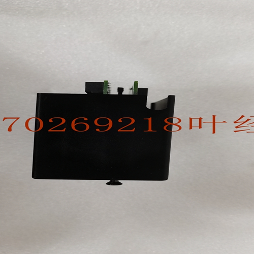
IS200TDBSH2ABC工控模块卡件
在下图中,冗余块的应用程序输出标记为“逻辑输出”。该数据之后是未投票区块的输出。n CPU将这些逻辑输出复制到输出表的底部。该数据在图中显示为容错输出,用于块的物理输出。这种物理输出与逻辑输出的分离防止了自动测试期间锁存器和密封电路等输出的中断。n每次总线扫描,总线控制器自动将未表决的输出加上复制的容错输出发送到Genius块。可用于单工输出容错输出保留存储器GMR逻辑应用程序容错输出设备无表决输出46632每个CPU离散输出表中的离散输出处理GMR输出组中的Genius块执行输出表决,如下页所述。关闭当GMR系统诊断出离散故障时,它会在故障表中记录相应的故障,并设置相应的故障触点。对于某些类型的离散故障,系统可选择为导致故障修复的问题留出预定义的时间。如果在这段时间内未纠正问题,则会关闭对应于受影响块的。关机定义为将受影响的设置为安全状态。对于输出,这是关闭状态。对于离散输入,关闭状态是GMR配置中输入组的“默认”状态。这对于每个输入组都是可选的。应用程序可以监视状态位,以了解未决关机,或完全防止关机发生。停机前的时间取决于为系统设置的自动测试间隔。初始自动测试间隔由GMR配置中选择的自动测试间隔值设置。通过改变自动测试间隔寄存器中的值,可以通过应用程序在每个CPU中调整配置的自动测试间隔。例如,当自动测试间隔设置为8小时时,系统允许故障发生和最终停机之间的总最长时间为24小时。2-8 Genius®模块冗余灵活三模块冗余(TMR)系统GFT-177A技术产品概述–1998年2月2输出子系统GMR系统的输出子系统部分可包括:n个输出组,由两个或四个汇点和源点DC离散Genius块组成,连接至多达32个执行器和其他现场输出设备n个单独的汇点和电源点DC离散的Genius块连接至多达32个现场输出设备,用于处理器冗余和脉冲测试。n其他类型的离散和模拟块,可提供热备用或双工PLC冗余。智能Genius Sink和Source DC块在内部输出表中存储多组输出。这些分组进行投票。投票方式可为应用程序配置。
In the illustration below, the application program outputs for redundant blocks are labeled “logic outputs”. This data is followed by outputs for non-voted blocks. n The CPU copies these logic outputs into the bottom portion of the Output Table. This data, shown as Fault-tolerant Outputs in the illustration, is used for physical outputs for the blocks. This separation of physical outputs from logical outputs prevents disruption of outputs such as latches and seal circuits during autotesting. n Each bus scan, the Bus Controllers automatically send the non-voted outputs plus the copied fault-tolerant outputs to the Genius blocks. Available for Simplex Outputs Fault-tolerant Outputs Reserved memory GMR Logic Application Program Fault-tolerant Output Devices Non-voted Outputs 46632 Discrete Output Processing in Each CPU Discrete Output Table The Genius blocks in GMR output groups perform output voting, as described on the following pages. Shutdown When the GMR system diagnoses a discrete fault, it logs the appropriate faults in its fault tables and sets appropriate fault contacts. For certain types of discrete faults, the system optionally allows a predefined amount of time for the problem that caused the fault to be repaired. If the problem is not rectified within this period of time, an Shutdown of the corresponding to the affected block(s) occurs. Shutdown is defined as setting the affected to its safe state. For outputs, this is the Off state. For discrete inputs, the shutdown state is the “default” state for an input group in the GMR configuration. This is selectable for each input group. The application program can monitor status bits to be made aware of a pending Shutdown, or to completely prevent an Shutdown from occurring. The period of time before an Shutdown occurs depends on the autotest interval which is set for the system. The initial autotest interval is set by the autotest interval value selected in the GMR configuration. The configured autotest interval can be adjusted in each CPU through the application program by varying the value in the autotest interval register. For example, the system allows a total maximum time of 24 hours between a fault occurring and the resultant shut down when the autotest interval is set to 8 hours. 2-8 Genius® Modular Redundancy Flexible Triple Modular Redundant (TMR) System GFT-177A Technical Product Overview – February 1998 2 Output Subsystem The output subsystem portion of a GMR system can include: n Output Groups of two or four Sink and Source DC discrete Genius blocks wired to up to 32 actuators and other field output devices n Individual Sink and Source DC discrete Genius blocks wired to up to 32 field output devices, for processor redundancy and pulse testing. n Other types of discrete and analog blocks, which can provide Hot Standby or Duplex PLC Redundancy. The intelligent Genius Sink and Source DC blocks store multiple sets of outputs in internal output tables. These block groups perform the voting. The manner of voting is configurable for the application.


