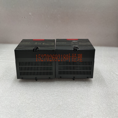
IS200TPROH1BCB模块卡件,处理器卡件
要求电缆的屏蔽层在电缆的整个长度上是连续的,包括在终端处。下图显示了在将电缆插入金属化外壳之前将编织屏蔽层向后折叠的推荐方法。分体式–环形卡套电缆护套接地连接至定制长度电缆的引脚1导线箔和编织物(在卡套和接地上折回)a45524或定制Y形电缆的折回。**有关何时将排水管连接到引脚1的说明,请参阅“早期远程底板版本的用户警报”。图B-2。如何为箔和编织电缆屏蔽使用开口环套圈对于典型的工业应用,所有扩展和远程底板电缆都可以用塑料外壳盖进行拆卸,并应如图10-19所示进行安装。在任何一种情况下,应将引脚1插入定制长度电缆的两端,并应遵循以下建议,在远程(IC693CHS392/399)底板中处理Y形电缆。当使用100%屏蔽电缆时,系统中的所有本地(和扩展)底板必须牢固地参考同一接地点,否则底板之间的电位差可能会干扰信号传输。早期远程基板版本的用户警报在早期远程基板版IC693CHS393E(及更早版本)和IC693CHS 399D(及更早)中,有必要移除电缆插入基板的连接电缆的引脚1。这意味着,当使用出厂的惠氏电缆(如IC693CBL300)时,必须在将引脚1与其中一个基板一起使用之前,将其从插入远程基板的一端断开。这些底板的定制Y形电缆应使用图10-20制作。输入/输出电缆数据表C GFK-0898F附录C–输入/输出线缆数据表C-7远程基板IC693CHS393F(及更高版本)和IC693CHS 399E(及更新版本)在基板内部进行了更改,从而无需从连接线缆上拆下引脚1。当使用带有这些底板的出厂de Wye电缆时,无需从电缆上拆下销1。可使用图10-20或图10-21对这些底板定制的Y形电缆进行拆卸。图10-21显示了标准(出厂)Y形电缆的设计。通过移除早期版本远程底板的定制Y形电缆中的引脚1,引脚7(0V)信号参考源于in()基板。在这些早期版本的远程底板中,引脚1连接到引脚7(0V),并且还AC耦合到远程机架接地。当将这些底板与100%屏蔽的Y形电缆结合使用时,引脚7(0V)参考将通过D超小型连接器外壳不正确地直流耦合到远程机架接地,该外壳直流耦合到远端机架接地。在远程底板IC693CHS393F(及更高版本)和IC693CHS 399E(及更低版本)中,引脚1屏蔽sigl直流耦合到远程机架接地,t连接到引脚7(0V)。
It is required that the cable’s shield be continuous across the entire length of the cable, including at the termitions. The figure below shows the recommended method for folding the braided shield back before inserting the cable into a metallized cover. Split–Ring Ferrule Cable Jacket Ground Attach to Pin 1 for custom length cables Conductors Foil & Braid (to be folded back over ferrule and ground ) a45524 OR Fold back for custom Wye cables. * * See “Alert for Users of Early Remote Baseplate Versions” for description of when to attach drain to pin 1. Figure B-2. How to use Split-Ring Ferrules for Foil and Braided Cable Shield For typical industrial applications, all expansion and remote baseplate cables can be de with plastic shell covers and should be d as shown in Figure 10-19. In either case, pin 1 should be d into both ends of the custom length cable and the recommendations listed below should be followed for the Wye cables treatment in the remote (IC693CHS392/399) baseplates. When using 100% shielded cables all local ( and expansion) baseplates in the system must be solidly referenced to the same ground point or a potential difference between baseplates could disturb sigl transmission. Alert for Users of Early Remote Baseplate Versions In early remote baseplates versions, IC693CHS393E (and earlier) and IC693CHS399D (and earlier), it is necessary to remove pin 1 of the ting cable where the cable plugs into the baseplate. This means that when using a factory de Wye cable, such as IC693CBL300, you must break pin 1 out of the le end where it plugs into the remote baseplate before using it with one of these baseplates. Custom built Wye cables for these baseplates should be built using Figure 10-20. I/O Cable Data Sheets C GFK-0898F Appendix C – I/O Cable Data Sheets C-7 Remote baseplates IC693CHS393F (and later) and IC693CHS399E (and later) have a change inside the baseplate which elimites the need to remove pin 1 from the ting cable. When using factory de Wye cable with these baseplates, it is t necessary to remove pin 1 from the cable. Custom built Wye cables for these baseplates can be de using either Figure 10-20 or Figure 10-21. Figure 10-21 shows how the standard (factory de) Wye cables are de. By removing pin 1 in custom built Wye cables de for the earlier versions of remote baseplates, the pin 7 (0V) sigl reference origites in the in () baseplate. In these earlier versions of the remote baseplates, pin 1 was tied to pin 7 (0V) and also AC coupled to the remote frame ground. When using these baseplates in combition with the 100% shielded Wye cables, the pin 7 (0V) reference would be improperly DC coupled to the remote frame ground through the D-subminiature connector shell, which is DC coupled to the remote frame ground. In the remote baseplates IC693CHS393F (and later) and IC693CHS399E (and later), the pin 1 shield sigl is DC coupled to the remote frame ground and t attached to pin 7 (0V).


