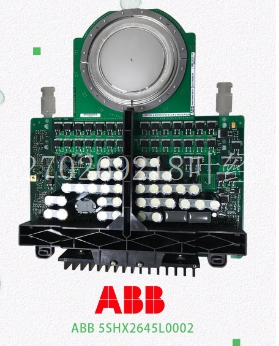
IS200TREGH1B处理器模块
如果取消inlid请求以更改报警值,则将在分配给模块的%I引用的第一个字节的四位高位返回相应的错误代码。E2示例以下梯形图逻辑提供了设置E2数据并发出的示例。与所有步骤一样,建议阶梯在启动之前验证E2的完成情况。这确保模块接收数据的速度不会超过处理数据的速度。执行此操作的一种方法是将状态(在本例中为%R0001)的内容归零。由于为已完成返回的状态从不为零,因此n-zero状态字将指示已完成。12 12-22系列90–30 PLC I/O模块规格–2000 GFK–0898F在此示例中,comnd块从%R0002开始,并在第一次扫描时初始化。假设发送到模块的6字节数据在ebled之前移动到%R0101–%R0103。模块位于机架0插槽2中,因此输入到的SYSID为0002。设置%T0001将零移动到状态字中,将%T0003设置为一次扫描以启动,并将%T0002设置为开始检查状态字。当检测到n零状态字时,将%T0002重置为停止检查,并将%T0004设置为指示模块已准备好进行下一次检查。如果发生故障,则设置参考%M0001。1in2 IN3 IN4 IN5 IN6 IN7 Q%R0001 CONST+00000在Q LEN 00001中移动单词00001 CONST E201%R0008 CONST 0006%R0009在Q lenn 00001中的移动INT在Q len00001中中移动INT在qlen 00004 CONST+0000 CONST+00008 CONST+00000fst_SCN FST_SCN%T0001 CONST+0008 CONST+00100 CONST+000000%R0010%R0011%R0001 S%T0002%T0003%T0001 R BLKINT IC693ALG442 Alog Combination I/O模块12 GFK–0898F第12章–IC693ALGA442 Alog Combination I/O模件12-23 INT Q COMM_ REQ S%M0001 IN FT SYSID TASK%R0002 CONST 0002 CONST 0000 CONST+00000 NE_ I1 I2%R0001 R S%T0002%T0004%T0002%T0003 12 12-24系列90–30 PLC I/O模块规格–2000 GFK–0.898F使用手持式编程器配置IC693ALG442使用Series 90-30手持式编程器的Alog电流/电压4-输入/2模块。除本节中的信息外,有关智能I/O模块配置的更多信息,请参阅GFK-0402F系列90-30/20/Micro可编程控制器用户手册或更高版本的手持式编程器第6章。模块存在如果系统中存在模块,则可以通过将该模块读入配置文件将其添加到系统的配置中。例如,假设一个4输入/2输出电流/电压模块安装在311型PLC系统的插槽3中。可以按以下顺序将其添加到配置中。箭头光标键或#键显示所选插槽。初始显示如果不想放弃所做的更改,请按CLR键。这将使您返回到上次修改的参数,所有更改都保持不变。如果您确实想放弃所做的更改,请按ENT键。然后,手持式编程器将返回到上次修改的参数,并将数据重置为先前的值。如果要从保存更改中将数据保存到?如上图所示,按下ENT键。
If an inlid request is de to change an alarm lue, the corresponding error code will be returned in the upper four bits of the first byte of %I references assigned to the module. E2 Example The following ladder logic provides an example of setting up E2 data and issuing the . As with all s, it is recommended that the ladder verify the completion of the E2 in progress before initiating ather. This ensures that the module does t receive s faster than it can process them. One way to do this is to zero the contents of the status (%R0001 in this example) as the is ebled. Since the status returned for a completed is never zero, a n-zero status word will then indicate that the has completed. 12 12-22 Series 90–30 PLC I/O Module Specifications – 2000 GFK–0898F In this example, the comnd block begins at %R0002 and is initialized on the first scan. It is assumed that the 6 bytes of data sent to the module are moved into %R0101–%R0103 before the is ebled. The module is located in rack 0, slot 2 so the SYSID input to the is 0002. Setting %T0001 moves zero into the status word, ebles %T0003 for one sweep to initiate the , and sets %T0002 to begin checking the status word. When a n-zero status word is detected, %T0002 is reset to discontinue checking and %T0004 is set to indicate that the module is ready for the next . Reference %M0001 is set if a fault occurs. IN1 IN2 IN3 IN4 IN5 IN6 IN7 Q %R0001 CONST +00000 MOVE WORD IN Q LEN 00001 MOVE WORD IN Q LEN 00001 CONST E201 %R0008 CONST 0006 %R0009 MOVE INT IN Q LEN 00001 MOVE INT IN Q LEN 00001 MOVE INT IN Q LEN 00001 CONST +00004 CONST +00000 CONST +00008 CONST +00000 CONST +00000 CONST +00000 FST_SCN FST_SCN %T0001 CONST +00008 CONST +00100 CONST +00000 %R0010 %R0011 %R0001 S %T0002 %T0003 %T0001 R BLK INT IC693ALG442 Alog Combition I/O Module 12 GFK–0898F Chapter12 – IC693ALG442 Alog Combition I/O Module 12-23 INT Q COMM_ REQ S %M0001 IN FT SYSID TASK %R0002 CONST 0002 CONST 0000 CONST +00000 NE_ I1 I2 %R0001 R S %T0002 %T0004 %T0002 %T0003 12 12-24 Series 90–30 PLC I/O Module Specifications – 2000 GFK–0898F Configuring IC693ALG442 with Hand-Held Programmer You can also configure the Alog Current/Voltage 4- Input/2- module using the Series 90-30 Hand-Held Programmer. In addition to the infortion in this section, refer to Chapter 6 of the Hand-Held Programmer for Series 90-30/20/Micro Programble Controllers User’s nual, GFK-0402F, or later version, for more infortion on configuration of Intelligent I/O modules. Module Present If a module is physically present in a system, it can be added to the system’s configuration by reading the module into the configuration file. For example, assume that an 4- Input/2- Alog Current/Voltage module is installed in slot 3 of a Model 311 PLC system. It can be added to the configuration with the following sequence. arrow cursor keys or the # key to display the selected slot. Initial Display you do t want to discard the changes you have de, press the CLR key. This will return you to the last parameter that was being modified with all changes intact. If you do want to discard the changes you have de, press the ENT key. The Hand-Held Programmer will then return you to the last parameter that was being modified with the data reset to its previous lue. If you want to save the data to the from the SAVE CHANGES? screen shown above, press the ENT key.


