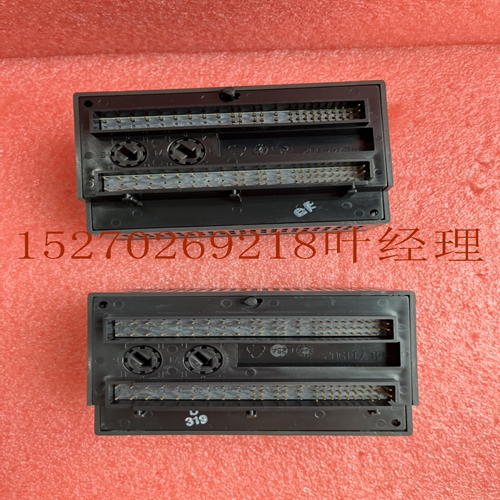
IS200TSVOH1BCC机器人卡件
例如,要将起始地址指定为I17,请按键序列1、7、ENT。将显示以下屏幕:R0:03 HI–DEN V>S I40:I17–I56选择%AI参考在选择了起始%I地址后,再次按下ENT键将显示如下屏幕:R0:0.3 HI–DEN V>S AI16:AI_此屏幕允许您为%AI参考选择起始地址。状态字段(16)的长度显示为显示器第二行上第一AI之后的前两位数字。te此字段不能用手持式编程器更改。但是,可以使用Logicster 90-30/20/Micro软件配置器功能对其进行更改。手持式编程器将始终反映状态字段的当前有效长度。在AI字段中,您可以通过按下ENT键或输入特定地址来选择下一个可用地址(默认)。要输入特定地址,请按起始参考数字键和ENT。钥匙(例如3、5,然后ENT.R0:03 HI–DEN V>S AI16:AI035–AI051)您可以随时按下CLR键中止刚刚选择的配置,并将插槽返回空。10 10-24 Series 90-30 PLC I/O模块规格–2000 GFK-0898F从配置中删除模块如果需要,可以从当前配置中删除此模块。假设模块当前为空配置在机架0插槽3中。可以按以下顺序删除:初始显示R0:03 HI–DEN V>S AI16:AI_要删除模块,请按DEL,ENT键顺序。然后显示为:R0:03 EMPTY>S Selecting Module Mode要显示模块模式,请按→ 钥匙显示屏将显示模块的当前模式。默认模式为单端。初始显示R0:03 HI–DEN V>S HI–DENV:SINGLE您可以通过按±键在单端模式和差分模式之间切换。将如图所示选择每种模式。所选范围是当前显示的范围。初始显示R0:03 HI–DEN V>S HI–DENV:差异当屏幕上显示模块所需的模式时,您可以通过按下ENT键选择该模式。选择输入范围可按如下所述显示、选择或更改16 s中每一个的范围。假设%AI地址与先前选择的相同。初始显示R0:03 HI–DEN V>S HI–DENV:SINGLE Alog输入模块10 GFK-0898F第10章–Alog输入模块10-25要显示范围,请按→ 钥匙显示屏将显示1(或当前选定的)和第一个可用范围。R0:03 HI–DEN V>S CHAN 1:0–10您可以通过按±键切换每个频道的范围。每个范围将显示如图所示。所选范围是当前显示的范围。R0:03 HI–DEN V>S CHAN 1:–10–10报警限值显示要查看当前显示的报警限值,请按→ 再次按键(第一次使范围可用于编辑)。显示以下屏幕:R0:03 HI–DEN V>S CH 1 LO:0显示为显示的低报警限的输入字段(在本例中为1)。您可以使用数字键和±键输入所需的低报警限值,以指定负值。使用表3-7中列出的盖限值内的数值输入低报警限值。输入低报警限值后,按下→ 再次按下此键,可显示高报警限值。此时将显示以下屏幕。R0:03 HI–DEN V>S CH 1:HI:32000显示屏显示当前显示的报警上限的输入字段。您可以使用±和数字键输入正数或负数(见表3-7)。选择1(或当前显示的)的低报警限值和高报警限值后,您可以按→ 钥匙R0:03 HI–DEN V>S CHAN 2:0–10编辑范围以及1中所述的低报警限值和高报警限值。所有活动的都可以在这一行中更改。按下ENT键或按下← 键,直到显示初始屏幕。10 10-26 Series 90-30 PLC I/O模块规格–2000 GFK-0898F保存的配置包含16-Alog电压输入模块的配置可以保存到EEPROM或MEM卡中,并在稍后读取。包含这些配置的MEM卡和EEPROM可以读取到任何版本4或更高版本中。有关保存和恢复操作的详细信息,请参阅手持式编程器用户手册第2章。Alog输入模块
For example to specify the starting address as I17, press the key sequence 1, 7, ENT. The following screen will be displayed: R0:03 HI–DEN V >S I40:I17–I56 Selecting %AI Reference After the starting %I address has been selected, pressing the ENT key again will cause the following screen to be displayed: R0:03 HI–DEN V >S AI16:AI_ This screen allows you to select the starting address for the %AI reference. te that the length of the status field (16) is displayed as the first two digits following the first AI on the second line of the display. te This field cant be changed with the Hand-Held programmer. However, it can be changed using the Logicster 90-30/20/Micro software configurator function. The Hand-Held Programmer will always reflect the currently active length of the status field. In the AI field you can select the next ailable address (the default) by pressing the ENT key or by entering a specific address. To enter a specific address, press the starting reference number keys and the ENT. key (for example 3, 5, then ENT. R0:03 HI–DEN V >S AI16:AI035–AI051 You can press the CLR key at any time to abort the configuration you have just selected and return the slot to EMPTY. 10 10-24 Series 90-30 PLC I/O Module Specifications – 2000 GFK-0898F Removing Module From Configuration If required, this module can be removed from the current configuration. Assume that the module is currently configured in rack 0, slot 3. It can be deleted with the following sequence: Initial Display R0:03 HI–DEN V >S AI16:AI_ To delete the module, press the DEL, ENT key sequence. The display will then be: R0:03 EMPTY >S Selecting Module Mode To display the module mode, press the → key. The display will show the current mode of the module. The default mode is Single Ended. Initial Display R0:03 HI–DEN V >S HI–DEN V:SINGLE You can toggle between the Single Ended and Differential modes by pressing the ± key. Each mode will be selected as shown. The range selected is the one currently displayed. Initial Display R0:03 HI–DEN V >S HI–DEN V:DIFFERE When the desired mode for the module is displayed on the screen you can selected it by pressing the ENT key. Selecting Input Ranges The range for each of the 16 s can be displayed and selected or changed as described below. Assume that the %AI address is as previously selected. Initial Display R0:03 HI–DEN V >S HI–DEN V:SINGLE Alog Input Modules 10 GFK-0898F Chapter 10 – Alog Input Modules 10-25 To display the ranges press the → key. The display will show 1 (or the currently selected ) and the first ailable range. R0:03 HI–DEN V >S CHAN 1: 0 – 10 You can toggle through the range for each by pressing the ± key. Each range will be displayed as shown. The range selected is the one currently displayed. R0:03 HI–DEN V >S CHAN 1:–10 – 10 Alarm Limits Display To view the alarm limits for the currently displayed, press the → key again (the first time caused the ranges to be ailable for editing). The following screen is displayed: R0:03 HI–DEN V >S CH 1 LO: 0 The display is the entry field for the low alarm limit for the displayed (in this case, 1). You can enter the desired low alarm limit lue using the numeric keys and the ± key for specifying negative lues. Enter the low alarm limit using a lue within the lid limits as listed in Table 3-7. After you have entered the low alarm limit lue, press the → key again to adnce to the high alarm limit display for this . The following screen is displayed at this time. R0:03 HI–DEN V >S CH 1: HI: 32000 The display shows the entry field for the high alarm limit for the currently displayed . You can enter positive or negative numbers (see table 3-7) using the ± and numeric keys. After selecting the low and high alarm limits for 1 (or the currently displayed ), you can view the next by pressing the → key. R0:03 HI–DEN V >S CHAN 2:0 – 10 Edit the range, and low and high alarm limits as described for 1. All active s can be changed in this nner. Return to the initial display screen by pressing the ENT key or by pressing the ← key until the initial screen is displayed. 10 10-26 Series 90-30 PLC I/O Module Specifications – 2000 GFK-0898F Saved Configurations Configurations that contain a 16- Alog Voltage Input module can be saved to an EEPROM or MEM card and read into the at a later time. MEM cards and EEPROMs containing these configurations can be read into any Release 4 or later . Refer to Chapter 2 of the Hand-Held Programmer User’s nual for detailed infortion on the Save and Restore operations. Alog Input Modules


