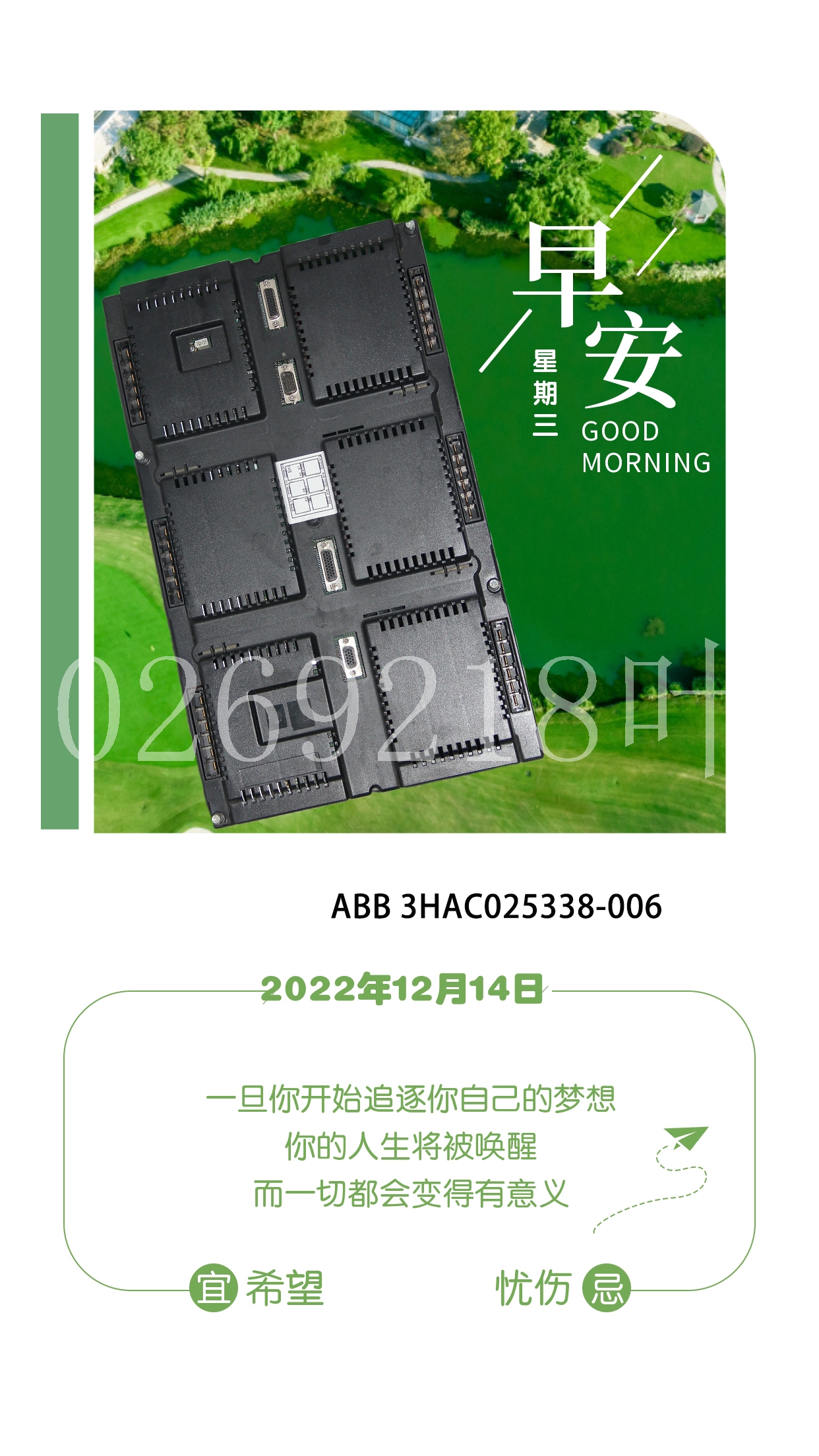
IS200VAICH1D系统模块卡件,工控模块卡件
4.75至5.25伏DC(TTL模式)10.2至28.8伏DC(12/24V模式),每个模块隔离32(四组,每组八个),场侧和逻辑侧之间1500伏,组间250伏,电流25每点关闭响应时间0.5毫秒,背板上5伏总线的互连功耗260;模块现场接线信息以下三个图提供了将用户提供的负载设备和电源连接到5/24伏直流负逻辑模块的接线信息。OCS MODE 1 MODE 0 5V 0V(FROM)xCOM PTx a45040 LOW–DROPOUT xVIN 10K 0V 5V LED稳压器运行模块下图中的点编号以粗体文本显示。用户TTL输入5V 24V 5V系列90-30 TTL输入图7-40。用户负载离散模块连接示例7 GFK-0898F第7章-离散模块7-47 IC693MDL752现场接线工作表下表是为了方便客户使用电缆IC693CBL315接线24针连接器。它在一个表格中包含所有所需的接线信息。此表包含以下信息:模块点编号:A1-A8、B1-B8、C1-C8、D1-D8、电压和点连接器引脚编号:A1至A12、B1至B12电缆编号:1至12颜色代码:基色或带示踪色的基色。还提供了列供参考和客户编号。接线5/24伏直流(TTL)负逻辑32点模块时,请根据需要复制并使用本页和下页的工作表。模块组A和B(模块右前方的连接器)的接线参考模块点号连接器引脚号电缆号颜色代码号0.5A系列90-30可编程逻辑控制器的正逻辑模块提供32个离散的s。s排列为四个独立的八组(A1-A8、B1-B8、C1-C8和D1-D8);每个组都有自己的。s是正逻辑或源类型s,因为它们切换电源正侧的负载,因此向负载提供电流。s可以在+12到+24(+20%,-15%)的范围内切换用户负载,并且能够提供每点0.5的电流。用户I/O连接器上为每组提供了两个引脚。每个引脚的电流处理能力为3安培。连接时,建议断开两个引脚的连接;然而,这是高电流应用(3至4安培之间)的要求。每组可用于驱动不同的负载。例如,A、B和C组可以驱动24个负载,而D组可以保留用于驱动12个负载。向负载提供电流的电源必须由用户提供。该模块还从用户电源汲取最小量的电力,以向设备提供栅极驱动。场侧和逻辑侧之间的背板隔离由模块上的光耦合器提供。停止时,所有32秒强制关闭。报告了特殊故障或报警诊断。模块顶部的LED指示灯(标记为A1-A8、B1-B8、C1-C8、D1-D8)提供每个点的开/关状态。该模块配置为32点类型,使用32位离散%Q数据。该模块可安装在Series 90-30 PLC系统中5或10插槽基板的任何I/O插槽中。
4.75 to 5.25 volts DC (TTL mode) 10.2 to 28.8 volts DC (12/24V mode) s per Module Isolation 32 (four groups of eight s each) 1500 volts between field side and logic side 250 volts between groups Current 25 per point Off Response Time 0.5 ms Interl Power Consumption 260 from 5 volt bus on backplane; Module Field Wiring Infortion The following three figures provide wiring infortion for connecting user supplied load devices and power source to the 5/24 volt DC negative logic module. OCS MODE 1 MODE 0 5V 0V (FROM ) xCOM PTx a45040 LOW–DROPOUT xVIN 10K 0V 5V LED REGULATOR RUN Module point numbers in the following figure are shown in bold text. USER TTL INPUT 5V 24V 5V SERIES 90-30 TTL INPUT Figure 7-40. Examples of Connections to User Loads Discrete Modules 7 GFK-0898F Chapter 7 – Discrete Modules 7-47 Field Wiring Work Sheet for IC693MDL752 The following table is provided for the convenience of our customers as an aid to wiring the 24-pin connectors using cable IC693CBL315. It includes all of the required wiring infortion in one table. This table has the following infortion: module point number: A1 - A8, B1 - B8, C1 - C8, D1 - D8, voltage and points connector pin number: A1 through A12, and B1 through B12 cable number: 1 through 12 color code: base color or base color with tracer color Columns are also provided for references and customer numbers. Please copy and use the work sheets on this and the following page as needed when wiring the 5/24 Volt DC (TTL) Negative Logic, 32 Point module. Wiring for Module Groups A and B (connector on right front of module) Reference Module Point Number Connector Pin Number Cable Number Color Code Number 0.5A Positive Logic module for the Series 90-30 Programble Logic Controller provides 32 discrete s. The s are arranged in four isolated groups of eight (A1 - A8, B1 - B8, C1 - C8, and D1 - D8); each group has its own . The s are positive logic or sourcing type s in that they switch the loads on the positive side of the power supply, and therefore supply current to the load. The s can switch user loads over the range of +12 through +24 (+20%, –15%) and are capable of sourcing a current of 0.5 per point. Two pins are provided on the user I/O connectors for each group . Each pin has a current handling capability of 3 amperes. It is recommended that connections are de to both pins when connecting the ; however, it is a requirement for high current applications (between 3 and 4 amperes). Each group can be used to drive different loads. For example, group A, B, and C can drive 24 loads, while group D can be reserved for driving 12 loads. Power to provide current to the loads must be provided by the user. The module also draws a minimum amount of power from the user supply to provide gate drive to the devices. Backplane isolation between the field side and logic side is provided by opto-couplers on the module. All 32 s are forced OFF when the is stopped. There are special fault or alarm diagstics reported. LED indicators (labeled A1 - A8, B1 - B8, C1 - C8, D1 - D8) at the top of the module provide the ON/OFF status of each point. This module is configured as a 32-point type and uses 32 bits of discrete %Q data. This module can be installed in any I/O slot of a 5 or 10-slot baseplate in a Series 90-30 PLC system.


