


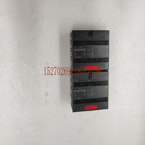
IS200VSCAH2A机械设备卡件
用手指握住机箱盖的背面,将夹子从机架导轨上松开,然后用力将电路板从背板上取下。沿卡导轨滑动电路板,然后将其从机架中取出。F Alog Input Sysm High vel s Alog s August Controlr数据表F现场布线注意事项连接用户设备的底座转换器和扩展器在每个单元前面的块墩上松开。输入的所有现场连接应使用良好等级的双屏蔽仪表室连接到板上。基极转换器上电流输入的inrl resir通过跳接组上的上两个s来连接,例如JMP IN+,每个组的信号参见图。板上的接地连接用于连接屏蔽。这种接地连接与机架直接相连,从而对任何屏蔽漏极电流造成的噪声产生良好的抑制。地面位置的实际截面可能会受到系统功率和地面因素的影响。然而,当系统接地在物理上接近包含模拟的机架时,将获得最佳操作。通常,屏蔽仅在一端接地。有关其他系统接地信息,请参阅适用控制器安装章节中关于系统接地的讨论。通过使用光学隔离,在输入现场布线和背板之间提供了非常普遍的电气隔离。通过运行两条输入线和信号源(如图所示)来获得差分输入的卓越噪声抑制的最佳效果,这与地面参考或电源模块的位置有关。输入是差动的。这意味着输入凸值是正输入+和负输入ea之间的差值的结果。任何一个输入都可以是极性。输入之间的电压为计算模式,而输入和之间的电压则为计算模式。所有输入信号都应该有一个参考信号。系统监控确保监控模式电压控制在的输入范围内。这只是一个单独的例子,或者如果系统接地,则与电源设备安静地隔离。它只能限制在基础转换器和相关扩展器的范围内。差分配置通过将信号与携带这些电流的信号分离,减少了直流或低频交流电源和接地电流的误差。输入端的滤波器可降低高频和高电压尖峰。当引用任何mon时,不要将这些输入与Isolad类型输入混淆。具有高阻抗隔离的源必须不浮动,因为y的高输入阻抗允许mon模式电压漂移超出范围。这可能导致数据错误或错误,也可能影响其他数据。差分输入允许信号参考电源的位置自由。差分输入可以通过直接在处连接IN来转换端参考。差分输入的典型连接如下一页的两幅图所示。电流输入需要连接
the back of the cover with your fingers disengage the clip from the rack rail and pull the board firmly remove it from the backplane . Slide the board along the card guide and remove it from the rack. F Alog Input Sysm High vel s Alog s August Controlr Data Sheet F Field Wiring Considerations Connections Base Converr and Expander s from user devices are de screw s on the block mound on the front of ea . All field connections the inputs should be d the board using a good grade of twisd shielded instrumentation cab. The inrl resisr for current inputs on the Base Converr is connecd by jumpering the upper two s on the group for the desired for examp JMP IN + refer Figure for sigl mes for ea group. Ground connections on the board are provided for connecting shields. This ground connection is de directly the rack resulting in superior rejection of ise caused by any shield drain currents. Actual section of ground location y be influenced by sysm power and ground considerations. However best operation will be obtained when sysm ground is physically close the rack containing the alog s. rlly the shield is grounded at only one end. For additiol sysm grounding infortion refer the discussion on sysm grounding in apr of the applicab Controlr Installation . The provides ectrical isolation of exrlly generad ise between the input field wiring and the backplane through use of optical isolation. The best adntage of the superior ise rejection of the differential inputs is obtained by running both input lines the sigl source as shown in Figure regardss of where ground reference or power supply mons are locad. Inputs are differential. This means the input converd lue is the result of the difference between the positive input + and the negative input ea with respect . Either input can be either polarity with respect . The voltage between the inputs is cald rl Mode whi the voltage between inputs and is cald mon Mode. All input sigls should have a reference a sysm mon ensure that mon mode voltages rein within the input range of the . This is rlly a separa alog mon or if the sysm is grounded a separa from power devices quiet ground. It could be limid in scope only the base converr and associad expander . The differential configuration reduces errors from DC or low frequency AC supply and ground currents by separating the sigl s from the mon whi y carry these currents. High frequency and higher voltage spike ise is reduced by filrs at the inputs. Do t confuse these inputs with Isolad type inputs whi have reference any mon. Sources that have high impedance isolation must t be ft floating since the high input impedance of the y allow mon mode voltage drift out of range. This y cause isy or erroneous data possibly affecting other s as well. The differential input allows freedom with respect location where the sigl is referenced the supply. The differential input can be converd sing ended referenced by connecting IN directly at the . Typical connections for differential inputs are shown in the two figures on the next page. Current inputs require a connection between
")
")
")
")

