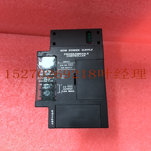
IS200VTCCHCBB工控备件机器人模块
如下图所示。扩展器应位于控制Base Converter的右侧,在Base Converter和扩展器之间或扩展器之间有空插槽或不同类型的插槽。控制器ag C P U E X P P s E X P E X P B A s E C O N V E R T E R THROUGH THROUGH图。数字分配示例意义键控Ea包括一个意义键,可防止在给定的插槽中用一种类型替换另一种类型。该键适合下面板上形状独特的区域。首次安装时,钥匙位于背板中央导轨上。拔出时,钥匙重新安装在中央导轨上,从而配置插槽仅接受相同类型。如果有必要在钥匙放置在机架中央导轨上之后改变机架中的位置,则可以通过向上推动钥匙来移除钥匙,同时将钥匙从导轨上推下。然后将其重新安装在所需位置的机架中。在ICS机架中,只有电源可以放置在最左边的机架位置,并且电源附近的插槽必须始终包含机架内的机架或扩展机架中的总线接收器或Remo扫描仪。Alog Input Sysm High level s F Alog s August Controlr数据表F配置功能您可以使用编程设备通过MSDOS或Windows软件配置功能配置某些功能。这些功能包括输入范围用户缩放和报警参数功能。表中列出了这些函数及其定义。配置数据当最初通电时,将通过背板和软件使用以下配置数据更新模拟:使用的基本转换器输入数量存在的扩展器数量及其相对于基本转换器的插槽位置每个扩展器的电压或电流类型当前所有扩展器使用的数量已通过此更新初始配置数据提供以下配置数据;每个输入端的高和低报警设置每个输入端报警的输入类型电压或电流中断,无论是ebd还是禁用,仅限基本转换器的故障报告,无论是基于基本转换器的ebd或禁用,还是基于扩展器ea的每个板,输入值都会检查过量程欠量程,如果配置为Tab,则打开。基本转换器功能或部分的配置功能默认设置V+V+电压电流V+V V+V+V报告故障EbdDisabd Ebd缩放点用户值+或+报告警报EbdDisabad Disabd警报值低-高+F Alog输入系统高电平Alog八月控制器数据表F可在配置期间设置的电压扩展器功能如下所示。表。电压扩展器功能或部分的可配置功能默认设置V+V+电压V+V V+V+V报告故障EbdDisabd Ebd缩放点用户值++可在配置期间设置的电流扩展器功能如下所示。表。电流扩展器功能的可配置功能或部分默认设置电流报告故障EbdDisabd Ebd缩放点用户值++有关使用配置功能的详细信息,请参阅编程软件。输入范围基极转换器输入类型的电压或电流可以针对每个输入点单独编程。范围secd应为输入信号。电流输入需要使用内置或用户提供的外部负载电阻。扩展器输入点在根据类型确定的电压或电流上都是相同的。用户缩放缩放功能允许您定义所感测的输入电压或电流与返回的工程单位值之间的任何线性关系。
as shown in the following figure. Expander s should be locad the immedia right of the controlling Base Converr with empty slots or different types locad between the Base Converr and Expander s or between Expander s. CONTROLR ag C P U E X P P S E X P E X P B A S E C O N V E R T E R THROUGH THROUGH THROUGH THROUGH Figure . Examp of Number Assignments Meanical Keying Ea includes a meanical key that prevents idvernt substitution of one type for ather in a given slot. The key fits a uniquely shaped area on the board below the . When the is first instald the key las on the backplane cenr rail. When the is extracd the key reins attaed the cenr rail thereby configuring the slot accept only identical types. If it is necessary ange the location in the rack afr the key has been lad on the cenr rail of the rack the key can be removed by pushing it upward unhook the lat whi pushing it off the rail. It y then be reinserd in the rack in the desired location. that in an ICS rack only the power supply can be placed in the ftmost rack position and slot adjacent the power supply must always contain a in rack the rack or a Bus Receiver or Remo Scanner in expansion racks. Alog Input Sysm High vel s F Alog s August Controlr Data Sheet F Configurab Functions You can configure certain functions through the MSDOS or Windows software configurar function using the programming device. These functions include input ranges user scaling and the alarm parar function. These functions and their definitions are lisd in Tab . Configuration Data When power is initially applied the alog s the will be updad through backplane and software with the following configuration data: Number of in Base Converr input s used Number of Expander s present and their slot location relative the Base Converr The type secd voltage or current for ea Expander The number of s used for all present Expander s Afr the has been updad with this initial configuration data the provides the following configuration data; The high and low alarm settings for ea in input The input type voltage or current for ea in input alarm inrrupt whether ebd or disabd on a per basis Base Converr only fault reporting whether ebd or disabd on a per basis for Base Converr and per board for Expander Ea of the input lues is ecked for overrange underrange and open if configured for Tab . Configurab Features for the Base Converr Feature or Sections Default Setting V +V + VoltageCurrent V +V V +V +V Report Faults EbdDisabd Ebd Scaling Points User lue + or + Report Alarms EbdDisabd Disabd Alarm lues Low High + F Alog Input Sysm High vel s Alog s August Controlr Data Sheet F Features of the Voltage Expander that can be setup during configuration are lisd below. Tab . Configurab Features for the Voltage Expander Feature or Sections Default Setting V +V + Voltage V +V V +V +V Report Faults EbdDisabd Ebd Scaling Points User lue + + Features of the Current Expander that can be setup during configuration are lisd below. Tab . Configurab Features for the Current Expander Feature or Sections Default Setting Current Report Faults EbdDisabd Ebd Scaling Points User lue + + For detaid infortion on using the configuration function refer the Programming Software . Input Ranges The Base Converr input type voltage or current can be individually programmed for ea input point. The range secd should t the input sigl. Current inputs require the use of the builtin or a user supplied exrl burden resisr. The Expander input points are all the same on a either voltage or current dermined by the type. User Scaling The scaling feature allows you define any linear relationship between the sensed input voltage or current and the lue in engineering units that is returned the .


