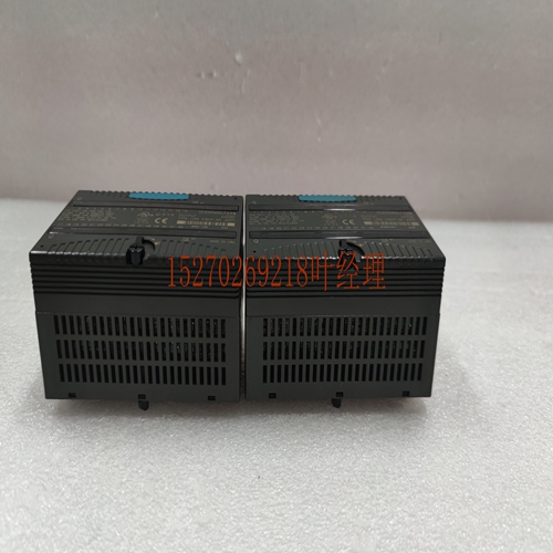
IS2020RKPSG1A模块控制器
我们将假设这些系统中的所有输入功率最终都被分解为热量。步骤是:在“规格”选项卡中查找“输入电流”的值。将输入电压乘以电流值乘以估计的持续时间百分比,得出该输入的平均功耗。Q附录F计算散热F F对上的所有输入重复。如果当前绘图和时间中有多个输入相似,则可以节省时间,这样您只需进行一次计算。对机架中的所有差异输入重复这些计算。差异输入检查:规格中的点差异C输入的规格选项卡提供以下信息:输入电流:典型rad电压下使用此值进行所有输入计算。在本例中,输入的八个点用于swis,而rl操作保持在关闭状态。其中包括紧急转速超温润滑压力正常和类似开关。使用公式平均功耗输入电压x输入电流(以x百分比表示),表示为时间的十分之一:x。每个输入x然后将这个结果乘以x个输入。在本例中,这一点上的两个输入点用于“控制开启”和“泵启动”按钮。在rl条件下,这些按钮每天只按一次,持续约一秒钟,直到启动控制器和泵。因此,它们对我们的功率计算的影响可以忽略不计,我们将假设它们的总输入功率耗散为零。为了控制我们六个点的六个输入,估计它们将在平均时间内打开。因此,对这六个输入进行以下计算:使用平均功耗输入电压x输入电流x百分比的公式,表示为时间的十分之一:x。每个输入x然后将这个结果乘以x个输入。输入的tal Filly加上我们得到的各个计算+.+对于总输入计算F安装和硬件8月Q F Sp:Fil计算一旦计算了单个功耗,将其相加,即可获得总散热量。在这个过程中,alog输入s和alog s被触发,因为与tal相比,它们的功耗值可以忽略不计。此外,由于每个机架都有自己的电源,因此每个机架都应单独计算。以下选项卡总结了fil计算:机架散热计算汇总Sp描述值计算机架中所有s的散热值总和除以Sp中获得的值除以电源值计算所有s的耗散值总和所有输入s的输入耗散值总和相加以上四个值获得机架的总散热值其他信息相关外壳尺寸这一部分包含机架尺寸和机架周围所需的最小通风距离。Cabs apr包含安装在s前部的驾驶室的carance尺寸。
We will assume that all input power delivered these s is eventually dissipad as heat. The procedure is: Find the lue for the Input Current in the Specifications tab for your input in the Specifications . Multiply the input voltage times the current lue times the estid percent of ontime arrive at average power dissipation for that input. Q Appendix F Calculating Heat Dissipation F F Repeat for all inputs on the . save time you could dermine if several inputs were similar in current draw and ontime so that you would only have ke their calculation once. Repeat these calculations for all Discre Input s in the rack. Discre Input Examp: The Specifications tab for the Point Discre C Input in the Specification gives the following infortion: Input Current: typical at rad voltage Use this lue for all of the input calculations for this . In this examp eight of the Input ’s points are used for swis that for rl operation stay on closed of the time. These include the Emergency Sp Over mperature Lube Pressure OK and similar swis. Use the formula Average Power Dissipation Input Voltage x Input Current in x Percent expressed as a decil of ontime: x . x per input Then multiply this result by x inputs . tal for the inputs Also in this examp two input points on this point are for the Control On and Pump Start pushbutns. Under rl conditions these pushbutns are only pressed once per day for about one second just long eugh start up the control and pump. Therefore their effect on our power calculation is negligib and we will assume a power dissipation of zero for them tal for inputs For the reining six inputs of our sixen point it is estid that they will be on for an average of of the time. So the following calculation is de for these six inputs: Using the formula of Average Power Dissipation Input Voltage x Input Current in x Percent expressed as a decil of ontime: x . x per input Then multiply this result by x inputs . tal for the inputs Filly adding up the individual calculations we get + . + for the ’s tal input calculation F Installation and Hardware August Q F Sp : Fil Calculation Once the individual power dissipations have been calculad add them all obtain tal heat dissipation. that the alog input s and alog s have been igred in this procedure because their power dissipation lues are negligib when pared with the tal. Also since ea rack has its own power supply ea rack should be calculad on an individual basis. The following tab sumrizes the fil calculation: Rack Heat Dissipation Calculation Sumry Sp Description lue Calcula tal of dissipation lues for all s in the rack Divide lue obtained in Sp by obtain Power Supply lue Calcula tal of all s’ dissipation lues Calcula tal of all Input s’ input dissipation lues Add the above four lues obtain the tal dissipation of the rack Other Infortion Relad Enclosure Sizing The s apr of this contains rack dimensions and minimum ventilation carance distances required around the racks. The Cabs apr contains carance dimensions for cabs that mount on the front of s.


