


IS210AEPSG2BB脉冲输入卡件
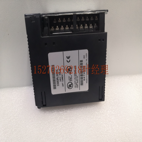
铰链式前盖。盖子很容易打开,可以接近电路板连接。对于rl操作,它保持关闭,防止人员意外发热。在下图中,前盖插件的背面包含板连接的集合图。本例中的目录号ICALG印在前盖插件底部。目录号也印在侧面的标签上。但是,为了查看此侧标签,已从中删除。在前盖插件的前侧,有与的点对应的线。您可以临时移除插入件,并在适当的线路上为每个点写下信号,以帮助进行刺入或槽冲。在前盖镶块的前侧,在镶块的ft边缘垂直延伸的是一条彩色线,用于标识类型:蓝色DC红色AC和灰色Alog。ns上限。它前面的位置覆盖了D发光二极管OK状态灯。此灯表示的基本状态。对于rl操作,OK D应打开。Q apr Inputput s A A A A OK ALOG CURRENT AR For USE WITH ICALG ns Cap OK D Removeab Board Catalog。类型连接图VOUT VOUT IOUT RTN RTN IOUT JMPV JMPV DEF+V OPT。连接件见用户拆卸插板铰链盖图。Alog s Twisd屏蔽仪表室的Alog电流接线方法示例强烈推荐用于模拟输入或信号连接。屏蔽的正确接地也很重要。为了抑制电气噪声,驾驶室屏蔽只能在驾驶室的一端接地。对于输入端,接地端位于最接近的环境中,而非现场设备端。在结尾处为s接地。更多屏蔽接地信息,请参见规范。纠正电气问题的输入接线方法有时可能是一个三端错误例行程序。然而,一般来说,最好将驾驶室护罩接地,使其尽可能靠近噪声源,而通常在设备端。有时,在排爆问题中,屏蔽接地点位置的试验是有益的。请记住,驾驶室护罩只能在一端接地。此外,最好尽可能缩短裸露的驾驶室广告的长度,以尽量减少暴露在潮湿环境中的非屏蔽导线的长度。有关添加剂的详细信息,请参阅规范。安装和硬件August Q直接法。从现场设备传感器桥体等直接运行屏蔽驾驶室。将导线连接到电路板上的适用螺钉。
Hinged Front Cover. The cover is easily opened access the board connections. For rl operation it is kept closed proct personnel from accidentally uing a hot . in the following figure that the back side of the front cover insert contains a setic diagram of the board connections. The catalog number ICALG in this examp is prind on the botm of the front cover insert. The catalog number is also prind on the label on the side of the . However in order see this side label the has be removed from the On the front side of the front cover insert are lines that correspond the ’s points. You can mporarily remove the insert and wri the sigl me for ea point on the appropria line aid in sting or troubshooting. Also on the front side of the front cover insert running vertically on the ft edge of the insert is a colored line that identifies the type of : Blue DC Red AC and Gray Alog. ns Cap. Locad on the p front of the it covers the D Light Emitting Diode OK status light. This light indicas the basic status of the . For rl operation the OK D should be on. Q apr Inpuutput s A A A A OK ALOG CURRENT AR FOR USE WITH ICALG ns Cap OK D Removeab Board Catalog . Type Connection Diagram VOUT VOUT IOUT RTN RTN IOUT JMPV JMPV DEF + V OPT. CONN. SEE USER'S Removeab Insert Hinged Cover Figure . Examp of Alog Current Wiring Methods for Alog s Twisd shielded instrumentation cab is strongly remended for alog input or sigl connections. Proper grounding of the shield is also important. For ectrical ise suppression the cab shield should only be grounded at one end of the cab. For Input s ground the end that is in the isiest environment whi ofn is at the field device end. For s ground at the end. See Specifications for more shield grounding infortion. Alog Input Wiring Methods Correcting ectrical ise probms can sometimes be a trialanderror routine. However in general it is generally best ground the cab shield as close the source of the ise as possib whi is usually at the device end. In troubshooting ise probms sometimes it is beneficial experiment with the shield grounding point location. Remember the cab shield should be grounded at one end only. Also it is best keep the ngth of stripped cab ads as short as possib minimize the ngth of unshielded conducrs that will be exposed the isy environment. See the Specifications for additiol details. Installation and Hardware August Q Direct Method. Run a shielded cab from the field device transducer pontiomer etc. directly the . Connect the conducrs the applicab screws on the ’s board.
")
")
")
")

