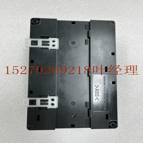
IS215ACLEH1C工控备件模块
安装和硬件八月Q月电源功能所有电源上的状态指示灯四个D位于电源面板的右上方。这些D的用途如下:PWR绿色D标记的PWR提供电源运行状态的指示。当电源具有正确的电源并且工作正常时,D接通;当电源故障或未通电时,D断开。OK(正常)如果操作正常,则第二个标有OK的绿色D为ON(打开),如果检测到问题,则为OFF(关闭)。RUN当处于RUN(运行)模式时,第三个标有RUN(运转)的绿色D指示灯处于ON(开启)状态。BATT如果在断电状态下内存中的备用电池电压过低,则底部红色D标记的BATT将亮起;否则,它将关闭。如果此D为ON,则必须在从机架上卸下电源之前更换锂电池,否则可能会丢失内存。输入过压保护装置本信息适用于除ICPWR和ICPWR外的所有电源。该电源的过电压保护装置连接在用户板上的插针内。当安装在工厂时,该引脚通常与提供的跳线带连接到机架接地引脚。如果不需要或上游提供过电压保护,可通过从引脚和上拆下跳线带来禁用此功能。如果您需要Hipot测试,则必须在测试期间通过移除跳线条带来禁用该电源过电压过程。通过重新安装扎带,重新启动过电压保护装置。Q apr电源跳线带连接过电压普氏装置框架接地螺钉板上框架接地图。过压保护装置和跳线带电压连接背板所有电源下图显示了这三个电压是如何连接到背板上的。安装在上所需的电压和功率通过s提供。电源背板DC-DC-RV-rpv-lf点连接单点连接,主要用于模拟输入模拟和直流输入,也可用于直流输入和用户应用电源前面的外部。主要用于继电器的外部连接接地。仅用于CPU输入等用途I V I图。电源安装和硬件连接八月Q过电流Proction所有电源V逻辑被电气限制。用于高容量电源。内部感应到包括短路在内的过载,并导致电源关闭。电源将继续尝试重新启动,直到过载消除。输入线路中的内部保险丝作为备用。电源通常会在保险丝熔断之前关闭。保险丝还可防止内部电源故障。时序图下面的时序图显示了DC输入和电源生成的电源OK信号PSOK之间的关系。当首次通电时,PSOK信号变为假。如果+V总线在规范范围内,则该线路在至少毫秒内为假,然后为真。如果输入电源中断,+V总线将在规范范围内控制,PSOK将在最少毫秒内控制为真。然后PSOK变为假。+V总线将控制在规格范围内
Installation and Hardware August Q Power Supply Feature The four D status indicators on all power supplies are located on the top right of the power panel. The purpose of these D's is as follows: PWR marked with green D provides indication of power supply operation status. When the power supply has correct power supply and works normally, D is connected; D is disconnected when the power supply fails or is not energized. OK If the operation is normal, the second green D marked OK is ON, or OFF if a problem is detected. RUN When in RUN mode, the third green D indicator marked RUN is ON. BATT If the voltage of the backup battery in the memory is too low when the power is off, the BATT marked with red D at the bottom will light up; Otherwise, it will close. If this D is ON, you must replace the lithium battery before removing the power supply from the rack, or you may lose memory. Input overvoltage protection device This information applies to all power supplies except ICPWR and ICPWR. The over-voltage protection device of the power supply is connected in the pin on the user board. When installed in the factory, this pin is usually connected to the frame ground pin with the jumper strip provided. If overvoltage protection is not required or provided upstream, this function can be disabled by removing jumpers from pins and. If you need Hipot test, you must disable the power supply overvoltage process by removing the jumper strip during the test. Restart the overvoltage protection device by reinstalling the tie. Q apr power jumper with overvoltage Proctor device frame grounding screw board upper frame grounding map. The figure below shows how the three voltages are connected to the backplane. The voltage and power required for installation on the are provided by s. The power backplane DC-DC-RV rpv lf point connection single point connection is mainly used for analog input analog and DC input, as well as DC input and the external front of the user application power supply. It is mainly used for external connection grounding of relay. I V I diagram is only used for CPU input and other purposes. Power supply installation and hardware connection August Q Overcurrent Procedure All power supply V logic is electrically limited. For high-capacity power supply. Overload, including short circuit, is sensed internally and causes the power supply to shut down. The power supply will continue to attempt to restart until the overload is removed. The internal fuse in the input line serves as a backup. The power supply is usually turned off before the fuse blows. Fuses also protect against internal power failure. The sequence diagram below the sequence diagram shows the relationship between the DC input and the power supply OK signal PSOK generated by the power supply. When power is applied for the first time, the PSOK signal becomes false. If the+V bus is within the specification range, the line is false for at least milliseconds and then true. If the input power supply is interrupted, the+V bus will be controlled within the specification range, and PSOK will be controlled to true within the minimum milliseconds. Then PSOK becomes false+ The V bus will be controlled within the specification range


