


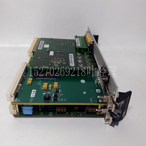
MVME172-243A工业自动化卡件
XOX配置不能用该运算符上的单个块完成(请参阅表2)。表5显示了如何获得XOX电路。在白色或黑色执行机构后面安装一个目录号800T-XA接触块,并将N.C.(盖上指定为“B”)和N.O.(盖上标记为“a”)触点并联连接。有关串联和并联图,请参阅第15页上的典型接线图。另一个例子是需要OXO电路的目录号800T-J2KE7操作员。请参阅第14页表5中的“KE7”凸轮和索引代码列。通过在白色执行机构后面安装目录号800T-XD2接触块和在黑色执行机构后面的目录号800T-XD2触点块,然后串联两个N.C.触点,可以获得OXO电路。第15页的表6显示了4个位置选择器开关的相同功能。4位选择开关示例(续)向现有设备添加触点公告800T油密选择开关产品数据14表5 3位选择开关功能➀ 操作员位置凸轮和索引代码标准位置查看KA1 KA7 KC1 KC7标准选择器开关从前执行器颜色执行器颜色致动器颜色执行器彩色开关(KB 7凸轮代码)前X=闭合O=打开白-黑-白-白-黑黑-黑-黑目录号800T-目录号800T-目录号800T--目录号 串联或并联电路由客户接线。
.
➁ 串联连接。➂ 并行布线。➃ 串联连接。当从位置2切换到位置3时,电路可能会暂时关闭。➄ 并行布线。从位置1切换到位置2时,电路可能会暂时断开。➅ 串联连接。当从位置1切换到位置2时,电路可能会暂时关闭。➆ 并行布线。从位置2切换到位置3时,电路可能会暂时断开。➇ 如有必要,可更换目录号800T-XD4的接触块。➈ 如有必要,可更换目录号800T-XD3的接触块。公告800T油密选择开关产品数据15表6 4位选择开关功能➀ 操作员位置凸轮和索引代码位置从前执行器彩色执行器彩色致动器彩色执行器颜色执行器彩色前X=闭合O=打开白-黑-白-白-黑黑-白黑-黑-黑目录号显示的串联或并联电路由客户接线。➁ 串联连接。➂ 并行布线。➃ 并行布线。从位置1切换到位置2时,电路可能会暂时断开。➄ 并行布线。从位置3切换到位置4时,电路可能会暂时断开。➅ 如有必要,可更换目录号800T-XD4的接触块。典型接线图串联或并联或➆ 串联和并联连接,如下图所示。➇ 串联和并联连接,如下图所示。将触点添加到现有设备(续)公告800T油密选择开关产品数据16触点配置可通过目标表方便地指示。请参阅第9页的表2和第11页的表4。4位置示例:从正面查看操作员位置。3位XOO OOX XOOO OXOO目标表提供每个给定选择器开关位置的触点状态。如以上示例所示,当从前面看选择器开关时,可以看到操作员的位置。每行表示电路的触点。
XOX configuration cannot be completed with a single block on this operator (see Table 2). Table 5 shows how to obtain XOX circuits. Install a catalog number 800T-XA contact block behind the white or black actuator and connect the N.C. (designated "B" on the cover) and N.O. (labeled "a" on the cover) contacts in parallel. For series and parallel diagrams, refer to the typical wiring diagram on page 15. Another example is the operator who needs the catalog number 800T-J2KE7 of the OXO circuit. Refer to "KE7" cam and index code column in Table 5 on page 14. The OXO circuit can be obtained by installing the catalog number 800T-XD2 contact block behind the white actuator and the catalog number 800T-XD2 contact block behind the black actuator, and then connecting two N.C. contacts in series. Table 6 on page 15 shows the same function of the four position selector switches. Example of 4-position selector switch (continued) Add contact bulletin 800T oil tight selector switch to existing equipment Product data 14 Table 5 3-position selector switch function ➀ Operator position cam and index code Standard position Check KA1 KA7 KC1 KC7 Standard selector switch Front actuator color Actuator color actuator color switch (KB 7 cam code) Front X=closed O=open white black white black black black catalog number 800T catalog number 800T catalog number 800T catalog number series or parallel circuit is wired by the customer.
.
➁ Series connection. ➂ Parallel wiring. ➃ Series connection. When switching from position 2 to position 3, the circuit may be temporarily closed. ➄ Parallel wiring. When switching from position 1 to position 2, the circuit may be temporarily disconnected. ➅ Series connection. When switching from position 1 to position 2, the circuit may be temporarily closed. ➆ Parallel wiring. When switching from position 2 to position 3, the circuit may temporarily open. ➇ If necessary, replace the contact block with catalog number 800T-XD4. ➈ If necessary, replace the contact block with catalog number 800T-XD3. Announcement 800T oil tight selector switch Product data 15 Table 6 4-digit selector switch function Operator position Cam and index code position Front actuator Color actuator Color actuator Color front X=Closed O=Open white black white black white black white black black black series or parallel circuits shown in the catalog number are wired by the customer. ➁ Series connection. ➂ Parallel wiring. ➃ Parallel wiring. When switching from position 1 to position 2, the circuit may be temporarily disconnected. ➄ Parallel wiring. When switching from position 3 to position 4, the circuit may temporarily open. ➅ If necessary, replace the contact block with catalog number 800T-XD4. Typical wiring diagram is series or parallel connection or series and parallel connection, as shown in the following figure. ➇ Series connection and parallel connection are shown in the figure below. Add contacts to existing equipment (continued) Bulletin 800T oil tight selector switch Product data 16 Contact configuration can be easily indicated through the target table. See Table 2 on page 9 and Table 4 on page 11. 4 Position example: View the operator's position from the front. The 3-bit XOO OOX XOOO OXOO target table provides the contact status for each given selector switch position. As shown in the above example, when you look at the selector switch from the front, you can see the position of the operator. Each line represents the contact of the circuit.
")
")
")
")
")
")
")

