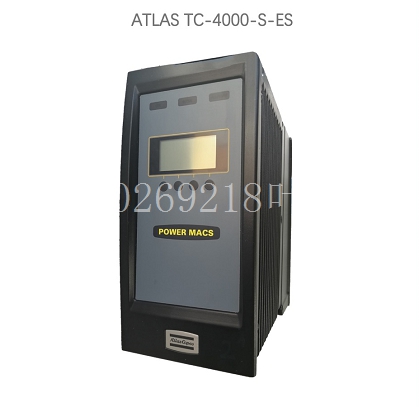
MVME172P-642LSE自动化模块备件
必须记录危险区域的尺寸和位置以及使用的假设,以便检查防护措施的充分性。如果其他防护措施与垫子系统一起使用,可能会影响确保盖子和格栅与地板表面齐平。无松散碎屑或突起。传感器垫不得下垂或起伏。没有锋利的边缘。传感器垫传感器垫16对垫的尺寸和位置的要求,如图11所示。图11。注意:固定防护装置应符合EN 953、EN 294和EN 811的要求。首先,确定需要穿过垫系统无障碍进入危险区域的路线。考虑所有日常访问需求,如产品检查、机器检查和调整、刀具更换和清除堵塞。还应考虑过程的视觉观察。在干预过程中,考虑机器附近人员和辅助设备的空间要求。安全距离计算对于使用垫子系统作为组合跳闸和存在感测系统的应用,应根据EN999进行计算。图12的流程图显示了基本步骤。注:如果机器的设计符合该机器的现有协调欧洲“C”型标准,该标准给出了具体公式或最小距离,则应优先使用EN 999中给出的公式。传感器垫危险危险传感器垫传感器垫固定防护延伸固定防护箭头显示通道17图12流程图显示方法计算的最小距离是传感器垫检测区外缘到危险最近部分的最小水平距离。地面安装式安全垫的EN 999公式为S=(1600 x T)+1200mm S是最小安全距离,单位为毫米。系数1600是基于进场速度1600mm/S的标准假设。T是以秒为单位的总停止时间。增加的1200mm是EN 999中给出的参数C,并考虑了步幅长度和手臂伸展。
是C类标准中是否给出了具体公式或最小距离?根据C类标准确定最小距离使用此最小距离根据prEN 999中的公式计算最小距离是否可以达到此最小距离?最小距离是否允许人员在危险区域内而不被发现?使用此最小距离以及根据风险采取的补充措施使用该最小距离是否可以缩短总体响应时间,或者是否可以缩短参数C?减少总响应时间和/或减少参数C使用附加或替代保护设备18总停止时间T由两部分组成:T=t1+t2 t1是启动传感功能和输出信号开关设备处于关闭状态之间的最长时间。对于垫子系统,t1=35mS。t2是机器的响应时间,即在接收到来自垫系统的输出之后停止机器或消除风险所需的时间。计算中使用的机器的响应时间需要是最坏情况下的时间。有些机器的响应时间不一致,这取决于操作模式、工件的性质以及启动停止的操作周期点。如果制动器等的磨损会影响响应时间,则应考虑磨损。在某些情况下,可能需要考虑机器控制系统的进一步延迟。计算示例在本示例中,垫子系统与最坏情况下响应时间测量为0.485秒的机器一起使用。使用公式,T=t1+t2=35mS+485mS=520mS=0.520S S=(1600 x 0.520)+1200mm=832+1200mm=2032mm从2032mm到机器底板边缘,需要传感器垫。5.4.2用作周界防护区域内的存在感测系统如果危险周围区域完全封闭在防护周界内,prEN 999的要求可能不适用。在这些应用中,垫子系统检测操作员的存在,以防止操作员在外壳内时重置周界防护系统并重新启动机器。
The size and location of the hazardous area and the assumptions used must be documented in order to check the adequacy of the protective measures. If other protective measures are used together with the mat subsystem, it may affect ensuring that the cover and grille are flush with the floor surface. No loose debris or protrusions. The sensor pad must not sag or fluctuate. No sharp edges. The requirements of sensor pad 16 on the size and position of the pad are shown in Figure 11. Figure 11. Note: The fixed protective device shall comply with the requirements of EN 953, EN 294 and EN 811. First, determine the route that needs to pass through the mat system to enter the hazardous area unobstructed. Consider all daily access needs, such as product inspection, machine inspection and adjustment, tool replacement, and removal of blockages. Visual observation of the process should also be considered. During the intervention, consider the space requirements for personnel and auxiliary equipment near the machine. Safety distance calculation For applications using the mat subsystem as a combined trip and presence sensing system, it shall be calculated according to EN999. The flowchart in Figure 12 shows the basic steps. Note: If the design of the machine complies with the existing harmonized European "C" standard for the machine, which gives a specific formula or a minimum distance, the formula given in EN 999 shall prevail. Sensor pad Hazard sensor pad Sensor pad Fixed protection Extended fixed protection arrow Display channel 17 Figure 12 Flow chart Display method The minimum distance calculated by the display method is the minimum horizontal distance from the outer edge of the sensor pad detection area to the nearest part of the hazard. The EN 999 formula of ground mounted safety pad is S=(1600 x T)+1200mm S is the minimum safety distance, and the unit is mm. The coefficient 1600 is a standard assumption based on the approach speed of 1600mm/S. T is the total stop time in seconds. The increased 1200mm is the parameter C given in EN 999, taking into account stride length and arm extension.
Is there a specific formula or minimum distance in the Class C standard? Determine the minimum distance according to the Class C standard Use this minimum distance to calculate the minimum distance according to the formula in prEN 999 Can you reach this minimum distance? Does the minimum distance allow people to stay in the hazardous area without being found? Can the use of this minimum distance and supplementary measures taken according to the risk reduce the overall response time, or can the parameter C be shortened? Reducing the total response time and/or reducing the parameter C using additional or alternative protective devices 18 The total stop time T consists of two parts: T=t1+t2 t1 is the longest time between starting the sensing function and closing the output signal switchgear. For mat subsystem, t1=35mS. T2 is the response time of the machine, that is, the time required to stop the machine or eliminate the risk after receiving the output from the cushion system. The response time of the machine used in the calculation needs to be the worst case time. Some machines have different response times, depending on the mode of operation, the nature of the piece, and the point at which the operation cycle starts and stops. If the wear of brakes, etc., affects the response time, wear should be considered. In some cases, further delays in the machine control system may need to be considered. Calculation Example In this example, the mat system is used with a machine that has a worst case response time measurement of 0.485 seconds. Using the formula, T=t1+t2=35mS+485mS=520mS=0.520S S=(1600 x 0.520)+1200mm=832+1200mm=2032mm from 2032mm to the edge of the machine floor, sensor pads are required. 5.4.2 The requirements of prEN 999 may not be applicable if the hazardous surrounding area is completely enclosed within the protective perimeter. In these applications, the mat subsystem detects the presence of the operator to prevent the operator from resetting the perimeter protection system and restarting the machine while inside the enclosure.
