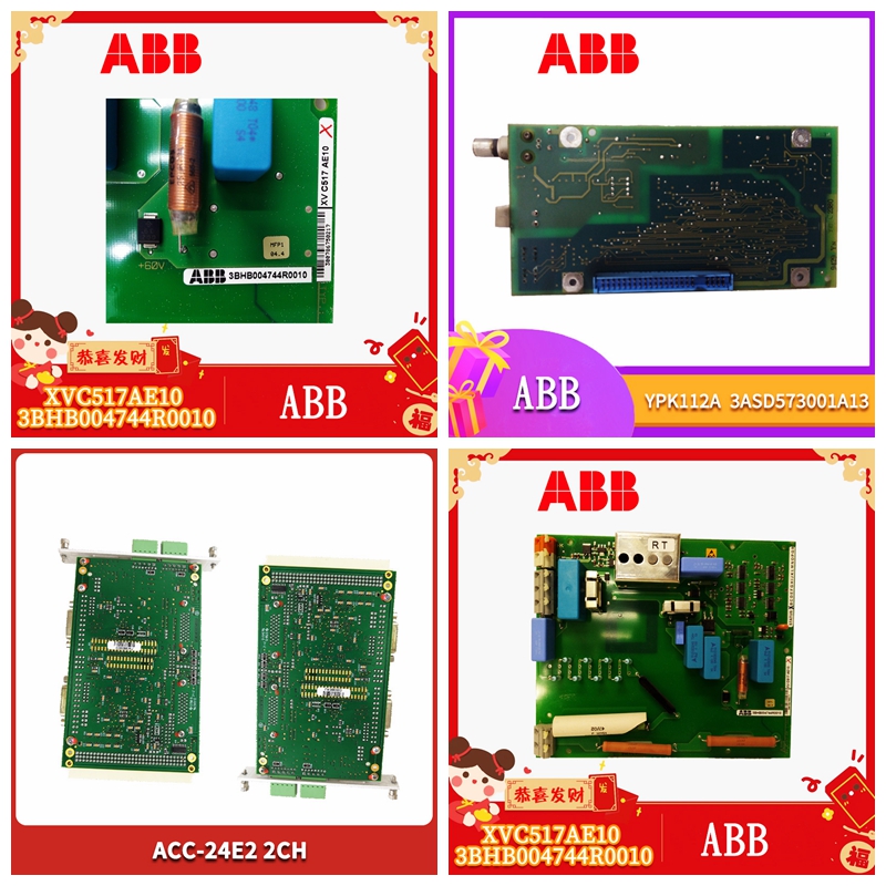
MVME172P-644LE工业自动化卡件
螺钉M2.5端子螺钉M3.5,45°安装,45°自举至PCB至PCB连接,垫圈端子板可单独拆卸安装组C,符合VDE 0110材料聚碳酸酯钢,带聚碳酸酯聚碳酸酯屏幕固定细节4 x M4孔4 x M6孔35mm,导轨其他。在手动复位N/A N/A模式(M)下,必须连接复位按钮外壳D=75mm D=143mm D=120mm H=180mm H=230mm H=73mm W=130mm W=210mm W=152mm 32路导轨重量880g 3200g 920g 10传感器垫传感器垫符合EN 1760-1,EN954-1:类别1,UL 508有保证检测的人的最小重量:35Kg最大检测区域:100m2单个垫的最大数量:无限制(最多100m2)连接线的最大总长度:200m质量/m2(传感器垫):24Kg环境保护垫:IP67机械寿命:1 x 106操作湿度:0-100%RH传感器垫外层材料:乙烯基标准颜色:黄色工作温度范围-10°C至+55°C存储温度范围-40°C至+70°C由互连传感器垫和控制单元组成的系统符合EN 954-1第3类的要求。11控制单元440F-C28013电源24V AC/DC或110/230V可选继电器输出2 x独立无电压N/O安全触点1 x独立无压N/C监控触点1 x免费N/C辅助触点1 x V免费N/O辅助触点安全输入8 x 4带模制Allen-Bradley连接器的线垫指示灯LED
1电源绿色LED 2手动复位模式绿色LED 3自动复位模式绿色LED4机器启用绿色LED 5-12信道故障状态绿色/红色端子减去与PCB成45°安装的M2.5端子螺钉注:适用于所有其他规格和尺寸详情请参考440F-C4000S控制单元。图7显示检测区的周边修剪和联合修剪详图。有关机器接口的指导,请参阅第5节。有关固定和互连安排的详细信息,请参阅6节。周边修剪主动装置修剪传感器垫检测区每个周边修剪增加52mm(NZG 3010)每个联合修剪接头增加10mm标称垫尺寸每个周边修剪(NZG 301 1)增加95mm 6 x 3/8”自攻螺钉(未提供)12图8尺寸单位为mm(英寸)-不按比例。152(6.0)35mm DIN导轨120(4.7)73(2.9)230(9.1)165(6.5)210(8.3)143(5.6)4 x M6 225(8.9)(0.23)11(0.43)130(5.2)75(3.0)4 x M4(0.16)113.5(4.5)180(7.1)10(0.39)11(0.33)163.5(6.4)使用盖子底部的固定孔13聚碳酸酯外壳440F-C4000P钢外壳440F-C4 000S和440F-C28013 DIN导轨外壳440F-C4000D第5节-安装设计开始安装前,应完整阅读本手册。建议装置只能由电气和机械工程方面具有适当能力并具有安全相关控制系统设计经验的人员设计。许多因素有助于安全可靠的安装。通过以下步骤的工作,将确保不会忽略任何内容,并且可以以最小的麻烦和最大的信心规划和实施安装。
Screw M2.5 Terminal screw M3.5, 45 ° installation, 45 ° self lifting to PCB to PCB connection, gasket terminal board can be separately disassembled and installed in group C, which conforms to VDE 0110 material polycarbonate steel, with polycarbonate polycarbonate screen fixing details 4 x M4 holes 4 x M6 holes 35mm, other rails. Under the manual reset N/A N/A mode (M), the reset button shell must be connected D=75mm D=143mm D=120mm H=180mm H=230mm H=73mm W=130mm W=152mm 32 way guide rail weight 880g 3200g 920g 10 sensor pad The sensor pad complies with EN 1760-1, EN954-1: Category 1, UL 508 Minimum weight of the person who can guarantee the detection: 35Kg Maximum detection area: 100m2 Maximum number of single pads: unlimited (maximum 100m2) Maximum total length of the connecting line: 200m mass/m2 (sensor pads) : 24Kg environmental protection pad: IP67 Mechanical life: 1 x 10⁶ Operating humidity: 0-100% RH Sensor pad Outer layer material: vinyl standard color: yellow Operating temperature range - 10 ° C to+55 ° C Storage temperature range - 40 ° C to+70 ° C The system consisting of interconnected sensor pads and control units complies with the requirements of EN 954-1 Category 3. 11 Control unit 440F-C28013 power supply 24V AC/DC or 110/230V optional relay output 2 x independent voltage free N/O safety contact 1 x independent voltage free N/C monitoring contact 1 x free N/C auxiliary contact 1 x V free N/O auxiliary contact safety input 8 x 4 wire pad indicator LED with molded Allen Bradley connector
1 Power supply green LED 2 Manual reset mode green LED 3 Automatic reset mode green LED 4 Machine enable green LED 5-12 Channel fault status green/red terminal minus M2.5 terminal screw installed at 45 ° to PCB Note: Applicable to all other specifications and dimensions, please refer to 440F-C4000S control unit for details. Figure 7 shows the peripheral trim and joint trim details of the detection area. Refer to Section 5 for instructions on machine interfaces. For more information on the fixing and interconnection arrangements, see Section 6. Peripheral trimming active device Trimming sensor pad Detection area Each peripheral trimming increases by 52mm (NZG 3010) Each joint trimming joint increases by 10mm Nominal pad size Each peripheral trimming (NZG 301 1) increases by 95mm 6 x 3/8 "self tapping screw (not provided) 12 Figure 8 Dimensions are in mm (inch) - not to scale. 152 (6.0) 35mm DIN rail 120 (4.7) 73 (2.9) 230 (9.1) 165 (6.5) 210 (8.3) 143 (5.6) 4 x M6 225 (8.9) (0.23) 11 (0.43) 130 (5.2) 75 (3.0) 4 x M4 (0.16) 113.5 (4.5) 180 (7.1) 10 (0.39) 11 (0.33) 163.5 (6.4) Use the fixing hole at the bottom of the cover 13 Polycarbonate housing 440F-C4000P steel housing 440F-C4 000S and 440F-C28,013 DIN rail housing 440F-C4000D Section 5 - Installation design Before installation, This manual should be read in its entirety. It is recommended that the device be designed only by personnel with appropriate competence in electrical and mechanical engineering and experience in the design of safety related control systems. Many factors contribute to a safe and reliable installation. The following steps will ensure that nothing will be ignored and the installation can be planned and implemented with minimum trouble and maximum confidence.


