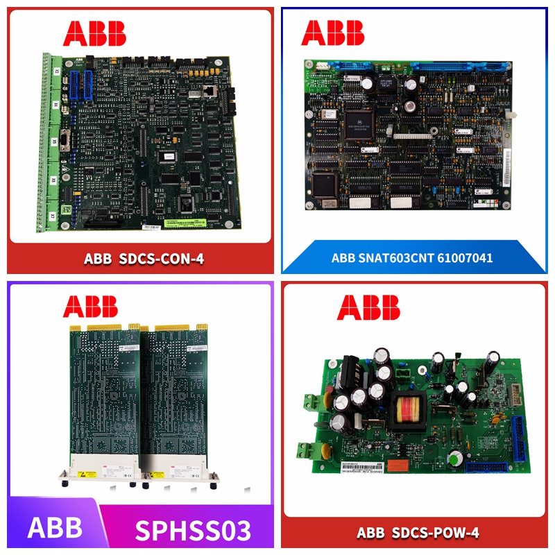
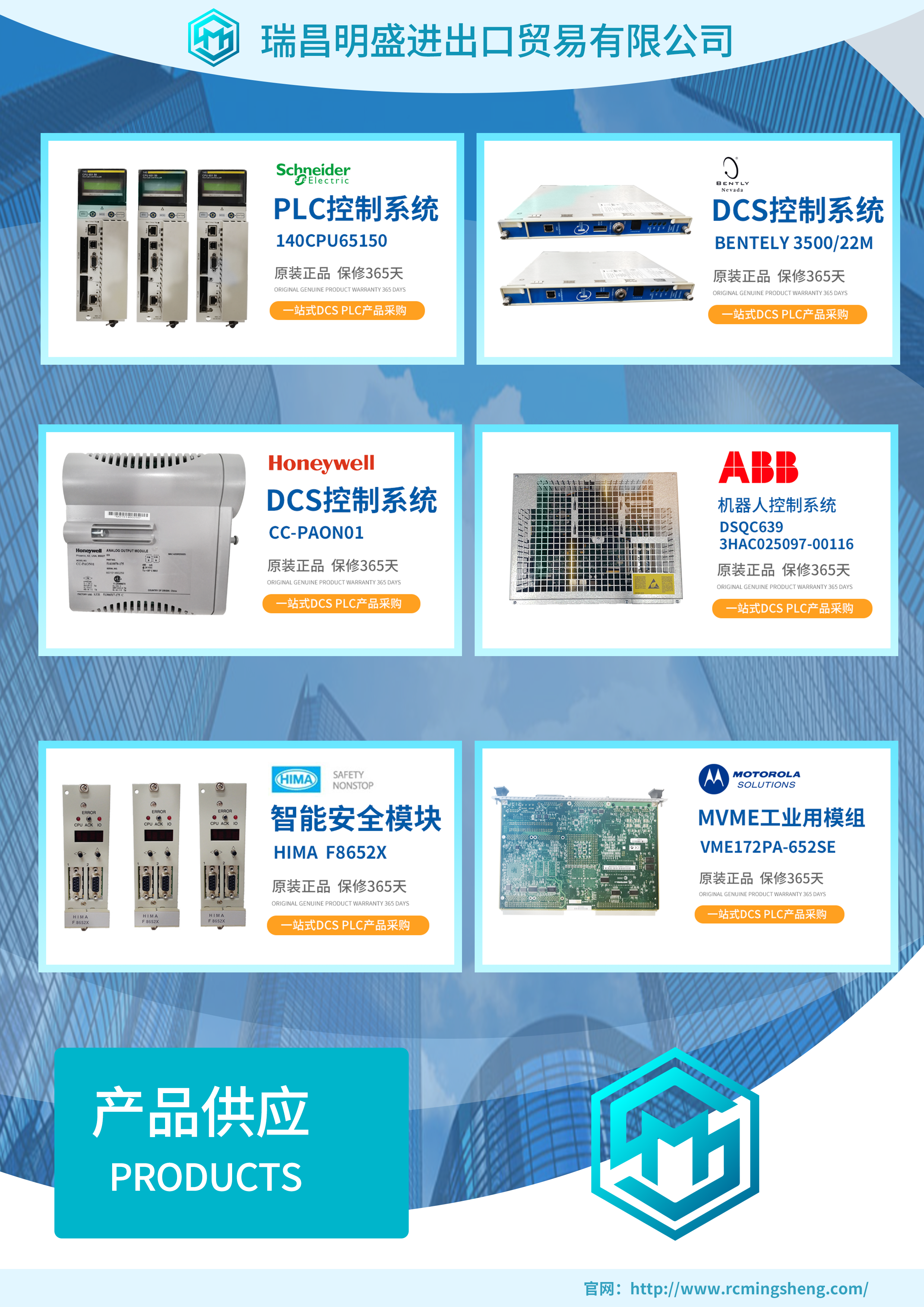
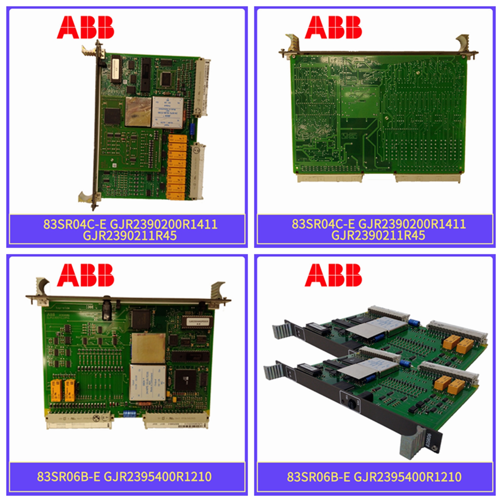
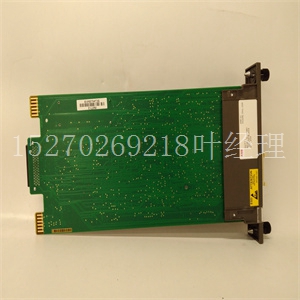
MVME2434-3工控备件机器人模块
建议的电源线尺寸3剥线长度7 mm(0.275 in。)4固定直流电源线的扭矩范围0.22…0.25 N•m(0.16…0.18 ft•lb)0.5…0.6 N•m(0.37…0.44 ft•lb安装说明图2-直流连接器组装顺序安装更换安装夹要更换VersaView 6300P面板PC和6300M显示器上的安装夹,请执行以下步骤。1.断开计算机或显示器的电源。2.将替换安装夹滑入电脑或显示器侧面的孔中,如右图所示。对于不同的孔位置,请参见第4.3页图3。按照第4.4页图3中的拧紧顺序手动拧紧安装夹。使用提供的1.5 mm六角扳手,按照第4.5页图3的拧紧顺序拧紧安装夹,按照第4.6页图3中的拧紧顺序,将安装卡箍拧紧至0.2 N•m(1.8 lb•in)的扭矩。重复此过程至少三次,直到卡箍正确拧紧至0.2 N.m(1.8磅•in)。确认垫片均匀地压在面板上。重要事项图2中所示的直流连接器组件仅用于说明目的。直流连接器组件的尺寸、形状和颜色可能与图2所示有所不同。
注意:将安装夹拧紧至规定扭矩,以提供适当的密封,并有助于防止产品损坏。罗克韦尔自动化公司对因安装不当而对外壳内的计算机或其他设备造成的水或化学损坏不承担任何责任。A B C D E F出版物6300V-IN003A-EN-P-2021 1月|取代出版物XXXX-X.X.X-年月版权所 。不属于Rockwel Automation的商标是其各自公司的财产。您的意见有助于我们更好地满足您的文档需求。如果您对如何改进我们的内容有任何建议,请在rok.auto/docfeedback填写表格。有关技术支持,请访问rok.auto/support*PN-618253*PN-618253废弃电气和电子设备(WEEE)罗克韦尔自动化公司在其网站rok.auto/pec上维护当前产品环境合规信息。在使用寿命结束时,该设备应与未分类的城市垃圾分开收集。图3-安装 .的紧固和扭矩顺序。,和17英寸。显示尺 和19英寸。显示尺寸I/O端口18.5英寸。显示尺寸10 ACI委员会440 ACI 440.2R-17报告的用于加固混凝土结构的外部粘结FRP系统的设计和施工指南2017年5月首次印刷ISBN:978-1-945487-59-0用于加固混凝土的外部粘结玻璃钢系统的设计与施工指南美国混凝土学会版权所有,密歇根州法明顿山。保留所有权利。未经ACI书面同意,不得在任何印刷、机械、电子、电影或其他分发和存储介质中复制或复制本材料的全部或部分内容。负责ACI委员会报告和标准的技术委员会努力避免这些文件中的歧义、遗漏和错误。尽管做出了这些努力,ACI文件的用户偶尔会发现信息或要求可能需要多个解释,或者可能不完整或不正确。
Recommended power cord size 3 Stripping length 7 mm (0.275 in.) 4 Fixed DC power cord torque range 0.22... 0.25 N • m (0.16... 0.18 ft • lb) 0.5... 0.6 N • m (0.37... 0.44 ft • lb installation instructions Figure 2 - DC connector assembly sequence Installation of replacement mounting clips To replace the mounting clips on the VersaView 6300P panel PC and 6300M monitor, perform the following steps. 1. Disconnect the power from the computer or monitor. 2. Slide the replacement mounting clips into the holes on the side of the computer or monitor, as shown in the right figure. For different hole locations, see Figure 3 on page 4.3. Manually tighten them according to the tightening sequence in Figure 3 on page 4.4 Tighten the mounting clip. Using the supplied 1.5 mm hex wrench, tighten the mounting clamp according to the tightening sequence shown in Figure 3 on page 4.5, and tighten the mounting clamp to a torque of 0.2 N • m (1.8 lb • in) according to the tightening sequence shown in Figure 3 on page 4.6. Repeat this process at least three times until the clamp is properly tightened to 0.2 N.m (1.8 lb • in). Confirm that the gasket is pressed evenly on the panel. IMPORTANT The DC connector assembly shown in Figure 2 is for illustrative purposes only. The size, shape, and color of the DC connector assembly may differ from those shown in Figure 2.
NOTE: Tighten the mounting clips to the specified torque to provide a proper seal and help prevent product damage. Rockwell Automation assumes no responsibility for water or chemical damage to computers or other equipment inside enclosures due to improper installation. A B C D E F Publication 6300V-IN003A-EN-P-2021 January | Supersedes publication XXXX-X.X.X-Copyright Office. Trademarks that are not part of Rockwell Automation are the property of their respective companies. Your comments will help us better meet your documentation needs. If you have any suggestions on how to improve our content, please fill in the form at rok.auto/docfeedback. For technical support, please visit rok Auto/support * PN-618253 * PN-618253 Waste Electrical and Electronic Equipment (WEEE) The current product environment compliance information is maintained on auto/pec. At the end of the service life, the equipment shall be collected separately from the unclassified urban garbage. Figure 3 - Tightening and torque sequence for installation., And 17 inches. Show ruler and 19 inches. Show size I/O port 18.5 inches. Guidelines for the Design and Construction of Externally Bonded FRP Systems for Strengthening Concrete Structures, Report of ACI Committee 440 ACI 440.2R-17, Size 10, was first printed in May 2017 ISBN: 978-1-945,487-59-0 Guidelines for the Design and Construction of Externally Bonded FRP Systems for Strengthening Concrete, American Concrete Institute, Farmington Hill, Michigan. All rights reserved. All rights reserved. This material may not be reproduced or reproduced in whole or in part in any print, mechanical, electronic, film or other distribution and storage media without the written consent of ACI. The Technical Committee responsible for ACI Committee reports and standards strives to avoid ambiguities, omissions and errors in these documents. Despite these efforts, users of ACI files occasionally find that information or requirements may require multiple interpretations, or may be incomplete or incorrect.
