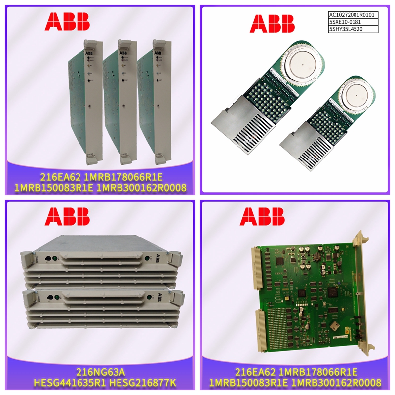
PFTL 101BER-20.0工控自动化卡件
3 m,方形端部440F-T3310铝制外角标准周边装饰件参见第2-99页440F-T3012铝制内角标准周边饰件440F-T3013铝制周边装饰件,带电缆槽。当多达8条电缆需要通过通道馈电时使用。2米,方形端部440F-T3211 3米,方形末端440F-T3311 4米,方形边缘440F-T3411带电缆槽的铝制外角周边饰件参见第2-99页440F-T3014带电缆槽内角周边饰件440F-T3015存在感测安全装置MatGuard™ 垫2-98请访问我们的网站:www.ab.com/catalogs出版物S117-CA001A-EN-P总则1-原则2-安全垫3-安全开关4-操作员界面5-逻辑R配件类型描述尺寸mm(in)Cat。编号:铝制直角周边饰件13 x 25 mm,2 m长(½x 1 in.,6.6 ft长)440F-T3216 13 x 25毫米,3米长(½x 1英寸,9.8英尺长)440F-T3316不锈钢角夹周边装饰件(每个包装5个)Ö5.5(0.22)7(0.28)10(0.39)20(0.79)45(1.8)440F-T102933不锈钢z形夹周边装饰物(每个包装1个)20(0.99)10(0.30)▸5.5(0.18)45(1.78)14.2(0.56)7,方形端部440F-T3120 1.5米(4.9英尺)长,方形端部440 F-T3020 2米(6.5英尺)长;方形端部4.4 F-T3220 3米(9.8英尺)长、方形端部44 F-T3320乙烯基导线导管63.5毫米(2.5英寸)宽、2米(6.6英尺)长440F-T3230 440F-C4000S和440FC4000P的配件套件。4个对接接头,2个500 mA保险丝,4个电线终端N/A 440F-A108433 12 Philips平头,用于440FA-3211和440FT3411通道内件的不锈钢螺钉。将顶部固定到底部#6 x 9.5(3/8)440F-A17143 12 Philips平头,带锚固件的不锈钢螺钉用于440F-T3210、440F-T3310和440FT3510装饰件#10 x 38(1.5)440F-A1-7141 12平头,带锚固件的不锈钢螺钉,用于440F-T321和440F-T3411通道装饰件#110 x 32(1.25)440F-A1 7142 4 3 1 2 DC Micro QD线组,4针1棕色2白色3蓝色4黑色2米(6.5英尺)889D-F4AC-2 5米(16.4英尺™ 垫2-99请访问我们的网站:www.ab.com/catalogs出版物S117-CA001A-EN-P总则1-原则2-安全垫3-安全开关4-操作员界面5-逻辑垫系统当需要一个以上的垫来保护一个区域时,使用以下尺寸来确定覆盖的区域有多大。在计算布局总面积时,请提供多个垫子的草图布局,添加“X”、“Y”和“Z”,以考虑周边装饰和接缝。主动联合修剪当施加压力时,联合修剪会导致垫子偏转并改变状态,因此即使在关节上也会产生整体灵敏度。(Z) -增加53.5 mm(2.1英寸)的标准周长镶边或99.5 mm(3.9英寸)的渠道镶边。(Y) -对于接头(X)尺寸A或B(X),尺寸A或C(Z),增加10 mm(0.4 in)-对于标准周边装饰,增加52 mm(2.0 in),对于通道装饰,增加99.5 mm(3.9 in)。总体尺寸标准周边装饰件内部和外部拐角通道尺寸43(1.7)43(1.7)53.5(2.1)53.5)2.1)96(3.8)96(38)14(0.55)11(0.43)14(055)标准周边装饰可容纳三根标准2线垫电缆或两根4线电缆。串联连接两个垫子时,需要相当于两根电缆。6带电缆通道内角和外角的周边镶边电缆通道尺寸99.5(3.9)44.5(1.8)44.4(1.8)144(5.7)99.5(3.9)144(5.7)42.2(1.66)14(0.55)9.2(0.36)电缆通道镶边可容纳多达8根标准2线垫电缆或7根4线电缆,即使在拐角处。尺寸单位为mm(in.)。尺寸不用于安装目的。近似尺寸重要事项使用第2-92页上的距离计算,以确保危险周围有足够的覆盖范围。存在感测安全装置MatGuard™ 垫2-100请访问我们的网站:www.ab.com/catalogs出版物S117-CA001A-EN-P概述1-原则2-安全垫3-安全开关4-操作员界面5-逻辑R连接双线电缆选项方格图案直线图案白色绝缘黑色绝缘白色绝缘黑色电绝缘注释:扁平电缆外径6.5 mm x 3.5 mm 4针微型M12连接器选项[mm(in.)]15(0.57)42(1.7)衬垫的花纹肋侧4 1 3 2直外螺纹衬垫的直肋侧连接电缆电缆出口配置代码描述兼容性连接器电线颜色电路A两条4.5 m(15 ft)2线电缆出口A角安全继电器黑色外护套白色绝缘黑色绝缘黑色N.C.B两条4.5米(15英尺)2线线缆出口B角安全继电器白色白色N.C.C一根9.1米(30英尺)4线电缆,带M12公接头,从左上角引出Mat Managers 4 1 3 2 1 Brow
3 m, square ends 440F-T3310 Aluminum external corner standard perimeter trim See page 2-99 440F-T3012 Aluminum internal corner standard perimeter trim 440F-T3013 Aluminum perimeter trim with cable channel. Used when up to 8 cables need to be fed through channel. 2 m, square ends 440F-T3211 3 m, square ends 440F-T3311 4 m, square ends 440F-T3411 Aluminium external corner perimeter trim with cable channel See page 2-99 440F-T3014 Internal corner perimeter trim with cable channel 440F-T3015 Presence Sensing Safety Devices MatGuard™ Mats 2-98 Visit our website: www.ab.com/catalogs Publication S117-CA001A-EN-P General 1-Principles 2-Safety Mats 3-Safety Switches 4-Operator Interface 5-Logic R Accessories Type Description Dimensions—mm (in) Cat. No. Aluminum right angle perimeter trim 13 x 25 mm, 2 m length (½ x 1 in., 6.6 ft length) 440F-T3216 13 x 25 mm, 3 m length (½ x 1 in., 9.8 ft length) 440F-T3316 Stainless steel angle clip perimeter trim (5 per package) Ø5.5 (0.22) 7 (0.28) 10 (0.39) 20 (0.79) 45 (1.8) 440F-T102933 Stainless steel z-clip perimeter trim (5 per package) 20 (0.79) 10 (0.39) Ø5.5 (0.22) 45(1.78) 14.2 (0.56) 7 (0.28) 440F-T102935 Active uniting trim (used to join two mats to ensure no dead spots) 1 m (3.28 ft) length, square ends 440F-T3120 1.5 m (4.9 ft) length, square ends 440F-T3020 2 m (6.5 ft) length, square ends 440F-T3220 3 m (9.8 ft) length, square ends 440F-T3320 Vinyl wire guide 63.5 mm (2.5 in.) width, 2 m (6.6 ft) length 440F-T3230 Accessories kit for 440F-C4000S and 440FC4000P. 4 butt splices, 2 500 mA fuses, 4 wire terminations N/A 440F-A108433 12 Philips flat head, stainless steel screws for 440FA-3211 and 440FT3411 channel trim. Secures top to the bottom. #6 x 9.5 (3/8) 440F-A17143 12 Philips flat head, stainless steel screws with anchors for 440F-T3210, 440F-T3310, and 440FT3510 trim #10 x 38 (1.5) 440F-A17141 12 flat head, stainless steel screws with anchors for 440F-T3211 and 440F-T3411 channel trim #10 x 32 (1.25) 440F-A17142 4 3 1 2 DC Micro QD Cordset, 4-pin 1 Brown 2 White 3 Blue 4 Black 2 m (6.5 ft) 889D-F4AC-2 5 m (16.4 ft) 889D-F4AC-5 10 m (32.8 ft) 889D-F4AC-10 15 m (49.2 ft) 889D-F4AC-15 20 m (65.6 ft) 889D-F4AC-20 30 m (98.4 ft) 889D-F4AC-30 Reset push button for Mat Manager controllers 800FP-FOPN3YX11 R Presence Sensing Safety Devices MatGuard™ Mats 2-99 Visit our website: www.ab.com/catalogs Publication S117-CA001A-EN-P General 1-Principles 2-Safety Mats 3-Safety Switches 4-Operator Interface 5-Logic Mat System When more than one mat is needed to protect an area, use the dimensions below to determine how large of an area is covered. PLEASE SUPPLY A SKETCH LAYOUT FOR MULTIPLE MATS When calculating the overall area of layout add ‘X’, ‘Y’ & ‘Z’ to allow for Perimeter trim and joints. Active Uniting Trim When pressure is applied, the uniting trim causes the mat to deflect and change state, therefore giving all over sensitivity even on the joints. (Z) - Add 53.5 mm (2.1 in) for Standard Perimeter Trim or 99.5 mm (3.9 in) for channel trim. (Y) - Add 10 mm (0.4 in) for joint (X) Dim A or B (X) Dim A or B (Z) - Add 52 mm (2.0 in) for Standard Perimeter Trim or 99.5 mm (3.9 in) for channel trim. Overall size Standard Perimeter Trim Internal and External Corners Channel Dimensions 43 (1.7) 43 (1.7) 53.5 (2.1) 53.5 (2.1) 96 (3.8) 96 (3.8) 14 (0.55) 11 (0.43) 14 (0.55) Standard perimeter trim holds three standard 2-wire mat cables or 2 4-wire cables. The equivalent of two cables are needed when connecting two mats in series. 6 Perimeter Trim with Cable Channel Internal and External Corners Channel Dimensions 99.5 (3.9) 44.5 (1.8) 44.5 (1.8) 144 (5.7) 99.5 (3.9) 144 (5.7) 42.2 (1.66) 14 (0.55) 9.2 (0.36) Cable channel trim holds up to 8 standard 2-wire mats cables or 7 4-wire cables even when going around corners. Dimensions are shown in mm (in.). Dimensions are not intended to be used for installation purposes. Approximate Dimensions IMPORTANT Use the Distance Calculation on page 2-92 to ensure adequate coverage around the hazard. Presence Sensing Safety Devices MatGuard™ Mats 2-100 Visit our website: www.ab.com/catalogs Publication S117-CA001A-EN-P General 1-Principles 2-Safety Mats 3-Safety Switches 4-Operator Interface 5-Logic R Connectivity Two-Wire Cable Option Checker Pattern Straight Pattern White Insulation Black Insulation White Insulation Black Insulation Note: Flat cable O.D. 6.5 mm x 3.5 mm 4-Pin Micro M12 Connector Option [mm (in.)] 15 (0.57) 42 (1.7) Checkered Rib Side of Mat 4 1 3 2 Straight Male Straight Rib Side of Mat Connection Cables Cable Exit Configuration Code Description Compatibility Connector Wire Color Circuit A Two 4.5 m (15 ft) 2-wire cables—exit out the A corners Safety Relays Black Outer Jacket White Insulation Black Insulation Black Black N.C. B Two 4.5 m (15 ft) 2-wire cables—exit out the B corners Safety Relays White White N.C. C One 9.1 m (30 ft) 4-wire cable with M12 male connector exits out of upper left corner Mat Managers 4 1 3 2 1 Brown 2 White N.C. 3 Blue 4 Black N.C. D One 9.1 m (30 ft) 4-wire cable without connector exits out of upper left corner Safety Relays 1 Brown 2 White N.C. 3 Blue 4 Black N.C. F One 0.76 m (2.5 ft) 4-wire cable with M12 male connector exits out of upper left corner Mat Managers 1 Brown 2 White N.C. 3 Blue 4 Black N.C. G One 9.1 m (30 ft) 4-wire cable with M12 male connector exits out of upper left corner Distribution Block (2 N.C.) 898D-4*LT-DM4 1 Brown 3 Blue N.C. 2 White 4 Black N.C. H One 9.1 m (30 ft) 5-wire cable with M12 male connector exits out of upper left corner ArmorBlock Guard I/O 5 4 3 1 2 1 Brown 2 White N.C. 4 Black 5 Grey N


