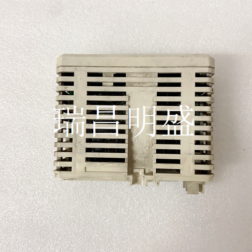
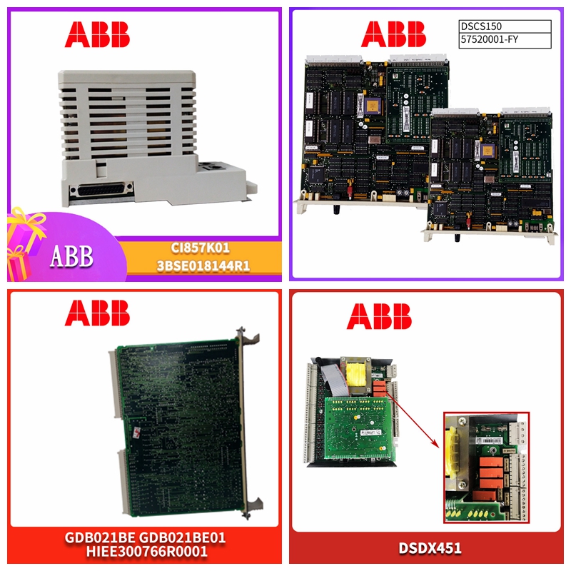
IMG_1626处理器模块
1 CAN H 2 CAN L 3 0V DC 4未连接5未连接6屏蔽(可选)7 CAN GND(可选)8 CAN V+(可选)输入2 PNP NPN PNP NPP D7 LED-电源CAN扩展PCB D3 LED输出1 D4 LED输出2 D8 LED D10 LED D6 LED输入2 D5 LED输入1 RJ45连接器发射器RJ45连接器接收器D2 LED输入1电位计1可拆卸弹簧加载连接器输入逻辑跳线S1 S2 J2 J12 J13输出1输出2输入1在2 n.c.地球。24 VDC 0 VDC 10罗克韦尔自动化出版物45MLA-IN002C-EN-P-2020年8月45MLA控制器安装说明电气连接J12和J13的各个引脚彼此串联(图9),并且相同。两条CAN电缆可以分别连接到两个插头,也可以仅连接到一个插头。CAN模块由内部供电。不使用CAN电源(接头J12和13,针脚7和8),而是串联连接。图9-CAN型号引脚状态指示器表24显示了CAN扩展PCB上状态指示器D8和D10的含义。DIP开关设置表25和表26描述了CAN型号的DIP开关的设置。扩展PCB上的DIP开关阵列S2(1…4)设置地址偏移,影响CAN标准模式和扩展CAN模式的所有基本地址。DIP开关设置更改仅在电源循环后生效。表24-CAN控制器状态指示灯状态指示灯描述颜色含义D8 CAN错误关闭无CAN错误红色CAN错误–无效消息D10 CAN通信关闭无通信绿色闪烁控制器通过CAN 1 2 3 4 5 6 7 8 CAN H CAN L C.GND C.SHIELD C.GND CAN V+1 2 3 4 6 7 8 CANH CAN L C GND C。GND CAN V+表25-DIP开关阵列S1设置功能阵列S1上的DIP开关编号(1)(1),(0:OFF,1:on,X:不相关),DIP 2…4未使用87654321默认值0 0 0 0 1 0 0 0偏移到地址:0(00 Hex)0 X 0 0 0
1 CAN H 2 CAN L 3 0V DC 4 Not connected 5 Not connected 6 Shield (optional) 7 CAN GND (optional) 8 CAN V+ (optional) In 2 PNP NPN PNP NPN D7 LED - Power CAN Extension PCB D3 LED Out 1 D4 LED Out 2 D8 LED D10 LED D6 LED In 2 D5 LED In 1 RJ45 Connector Emitter RJ45 Connector Receiver D2 LED D1 LED In 1 Pot 2 Pot 1 Removable Spring-Loaded Connector Input Logic Jumpers S1 S2 J2 J12 J13 Out 1 Out 2 In 1 In 2 n. c. Earth. 24 VDC 0 VDC 10 Rockwell Automation Publication 45MLA-IN002C-EN-P - August 2020 45MLA Controller Installation Instructions Electrical Connection The individual pins from J12 and J13 are connected to each other in series (Figure 9) and are identical. Two CAN cables can be connected to the two plugs separately, or connected to just one plug. The CAN module is powered internally. The CAN power supply (connector J12 and 13, Pin 7 and 8) is not used, but connected in series. Figure 9 - CAN Model Pinout Status Indicators Table 24 shows the meaning of status indicators D8 and D10 on the CAN extension PCB. DIP Switch Settings Table 25 and Table 26 describe DIP switch settings for the CAN model. DIP switch array S2 (1…4), on the extension PCB, sets the address offset, affecting all basic addresses from the CAN standard mode and extended CAN mode. DIP switch setting changes only take effect after a power cycle. Table 24 - CAN Controller Status Indicators Status Indicator Description Color Meaning D8 CAN Error Off No CAN error Red CAN error – invalid message D10 CAN Communication Off No communication Green flashing Controller communicating over CAN 1 2 3 4 5 6 7 8 CAN H CAN L C. GND C. SHIELD C. GND CAN V+ 1 2 3 4 5 6 7 8 CAN H CAN L C. GND C. SHIELD C. GND CAN V+ Table 25 - DIP Switch Array S1 Setting Function DIP switch number on array S1 (1) (1) (0: OFF, 1: ON, X: not relevant), DIP 2…4 not used 87654321 Default 0 0 0 0 0 0 0 0 Offset to address: 0 (00 Hex) 0 X X X 0 0 0 0 Offset to


