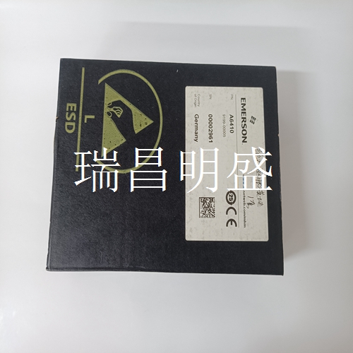
EMERSON A6410 系统模块卡件
重置默认参数设置所有控制器都带有默认参数值,可通过I/O型号的示教过程和RS-485和can型号的串行命令更改这些默认参数值。所有型号的默认参数都可以通过以下步骤重置:1.关闭控制器电源。2.将DIP开关阵列S1上的开关8设置为on。3.打开控制器电源。4.将DIP开关阵列S1上的开关8设置为OFF。5.现在应恢复默认设置。功能描述-模拟模型图3-模拟模型模拟控制器模型提供与目标高度、宽度或位置成比例的4…20 mA或0…10V(电流或电压可通过DIP开关选择)输出。输出会自动缩放到连接阵列的长度,因此大多数应用程序不需要额外调整。需要定制输出比例的应用程序可使用“示教”按钮。引脚列表表6显示了主连接器J2上的引脚分配。表4-控制器主板状态指示器状态指示器描述颜色含义D1灯阵列正常关闭目标存在或灯阵列未对齐绿色目标不存在和灯阵列对齐绿色闪烁低裕度/光强度不足D2灯阵列状态关闭目标不存在红色目标存在红色闪烁系统D3输出1关闭输出1关闭绿色输出1激活D4输出2关闭输出2非激活绿色输出2激活D5输入1关闭输入1非激活绿色输入1激活D6输入2关闭输入2非激活绿输入2激活D7电源关闭电源关闭绿色电源打开表5-控制器主PCB电位计调整电位计描述方向限值电位计1(1)(1)电位计1未用于模拟控制器型号。Reset Default Parameter Settings All controllers are shipped with default parameter values that can be changed through the teach process for the I/O model and through serial commands for the RS-485 and CAN models. The default parameters can be reset in all models by following this procedure: 1. Turn off controller power. 2. Set switch 8 on DIP switch array S1 to ON. 3. Turn on controller power. 4. Set switch eight on DIP switch array S1 to OFF. 5. Default settings should now be restored. Functional Description — Analog Model Figure 3 - Analog Model The analog controller model offers either 4…20 mA or 0…10V (current or voltage selectable via DIP switch) output proportional to target height, width, or position. The output is automatically scaled to the length of the connected arrays, so most applications do not require additional adjustments. A Teach button is available for applications that require customized scaling of the output. Pin Listings Table 6 shows the allocation of pins on the main connector, J2. Table 4 - Controller Main Board Status Indicators Status Indicator Description Color Meaning D1 Light array OK Off Target present or light arrays not aligned Green Target not present and light arrays aligned Green flashing Low margin/light intensity inadequate D2 Light array status Off Target not present Red Target present Red flashing System D3 Out1 Off Output 1 inactive Green Output 1 active D4 Out2 Off Output 2 inactive Green Output 2 active D5 In1 Off Input 1 inactive Green Input 1 active D6 In2 Off Input 2 inactive Green Input 2 active D7 Power Off Power off Green Power on Table 5 - Controller Main PCB Potentiometer Adjustments Pot Description Direction Limit Value Pot 1 (1) (1) Potentiometer 1 is not used on the analog controller model.


