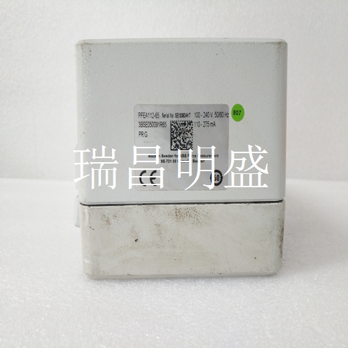
ABB PFEA112-65 3BSE050091R65 工控模块系统备件
45MLA-IN002C-EN-P-2020年8月5 45MLA控制器安装说明•在示教过程中随时关闭电源可取消该过程。先前存储的值仍然有效。•模拟输出在示教过程中处于激活状态,输出值表示基于电流中断光束和当前示教过程期间示教值的实际状态。•通过将DIP开关1:8设置为ON并循环电源,可以重置默认值(模拟输出缩放到连接的灯阵列的全长)。•将不同长度的光阵列对连接到控制器会导致模拟输出缩放到阵列的整个长度,从而覆盖最小和最大模拟输出值的任何设定值。•通过改变在示教过程中呈现两个不同大小对象的顺序,可以使模拟输出的斜率为正或负。例如,在步骤2中呈现较高的对象而在步骤3中呈现较短的对象会导致模拟输出中的负斜率。功能描述-基本模型图4-基本模型该控制器模型提供一个基本的离散(开/关)输出,指示阵列的整体状态。引脚列表表10显示了主连接器J2上的引脚分配。S1 DIP开关阵列上的DIP开关设置DIP开关1…6配置用于表11中所述的各种应用。如果没有其他信息,这些DIP开关应保持在OFF位置。DIP开关8用于重置默认配置。一旦更改,DI开关设置仅在电源循环后才被识别。表11详细说明了I/O板的DIP开关设置。有关所列功能的更多信息,请参阅出版物10000071139。45MLA控制器的设计范围至少为4米(13.1英尺)。因此,一些半透明目标可能无法阻挡足够的光线,无法被正确检测,特别是当发射器和接收器阵列放置得更近时。使用基本控制器模型,可以使用DIP开关降低发射器强度,从而更容易检测半透明对象。
45MLA-IN002C-EN-P-20 August 5, 2020 45MLA controller installation instructions • Turn off the power at any time during the teaching process to cancel the process. The previously stored values are still valid. • The analog output is active during the teaching process, and the output value represents the actual state based on the current interruption of the beam and the teaching value during the current teaching process. • By setting the DIP switch 1:8 to ON and cycling the power, you can reset the default value (the analog output is scaled to the full length of the connected lamp array). • Connecting pairs of optical arrays of different lengths to the controller causes the analog output to scale to the entire length of the array, overwriting any setpoint for the minimum and maximum analog output values. • By changing the order in which two objects of different sizes are presented in the teaching process, the slope of the analog output can be positive or negative. For example, rendering a higher object in step 2 and a shorter object in step 3 results in a negative slope in the analog output. Function Description - Basic Model Figure 4 - Basic Model The controller model provides a basic discrete (on/off) output indicating the overall state of the array. Table 10 of the pin list shows the pin assignments on the main connector J2. DIP switch settings on the S1 DIP switch array DIP switches 1... 6 are configured for various applications described in Table 11. If there is no other information, these DIP switches should remain in the OFF position. DIP switch 8 is used to reset the default configuration. Once changed, the DI switch settings are recognized only after the power cycle. Table 11 details the DIP switch settings for the I/O board. For more information on the features listed, refer to publication 10000071139. The design range of the 45MLA controller shall be at least 4 meters (13.1 feet). Therefore, some translucent targets may not block enough light to be detected correctly, especially when the transmitter and receiver arrays are placed closer. With the basic controller model, you can use DIP switches to reduce emitter strength, making it easier to detect translucent objects.


