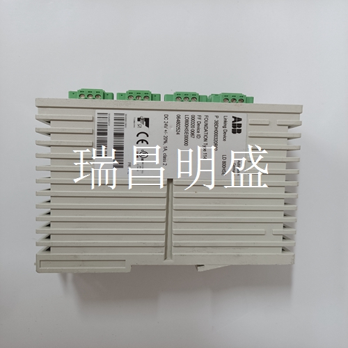
ABB LD800HSE 3BDH000320R02 机器人模块
基本控制器(仅当选择双扫描模式时,例如通过DIP开关4)。逆时针t_ot=0 s顺时针t_ot=3.3 s Pot2最小输出持续时间逆时针t_out=0 s顺时钟t_out=3.3 s表6-J2引脚列表引脚信号说明备注1 0V DC电源-2+24V DC电源-3接地-4未连接未连接-5输入2未使用-6输入1未使用DIP开关S1(3)=0远程示教DIP开关S2(3)=1 7输出2错误0V DC=错误24V DC=无错误8输出1灯阵列中断0V DC=中断24V DC=未中断输入2 PNP NPN PNP NPP D7 LED-电源模拟扩展PCB D3 LED输出1 D4 LED输出2 D6 LED输入2 D5 LED输入1 D13 LED D15 LED D12 LED D11 LED D10 LED RJ45连接器发射器RJ45连接器接收器D2 LED输入1电位计2电位计1示教按钮可拆卸弹簧加载连接器输入逻辑跳线S1J2 J15输出1输出2输入1输入2 n.c.接地。24 VDC 0 VDC D16 LED 4罗克韦尔自动化出版物45MLA-IN002C-EN-P-2020年8月45MLA控制器安装说明表7显示了I/O扩展PCB上的引脚分配。状态指示器表8显示了扩展PCB上状态指示器D15和D16的含义。DIP开关设置S1 DIP开关阵列上的DIP开关1…6配置用于表9中所述的各种应用。如果没有其他信息,这些DIP开关应保持在OFF位置。DIP开关8用于重置默认配置。下表详细介绍了I/O板的DIP开关设置。有关所列功能的更多信息,请参阅出版物10000071139。可以将模拟控制器配置为忽略短光束中断,例如通过检测区域的小颗粒引起的短光束中断。通过打开DIP开关4可启用双扫描模式。在此模式下,每个光束都会被评估两次(而不是一次),只有在两次评估期间中断的光束才会被识别。
Basic controller (only when dual scan mode is selected, e.g. via DIP switch 4). Counterclockwise t_ Ot=0 s clockwise t_ Ot=3.3 s Pot2 minimum output duration counterclockwise t_ Out=0 s clockwise t_ Out=3.3 s Table 6-J2 Pin List Pin Signal Description Remarks 1 0V DC power supply - 2+24V DC power supply - 3 grounding - 4 not connected and not connected - 5 input 2 not used - 6 input 1 not used DIP switch S1 (3)=0 remote teaching DIP switch S2 (3) =1 7 output 2 error 0V DC=error 24V DC=no error 8 output 1 lamp array interrupt 0V DC=interrupt 24V DC=no interrupt input 2 PNP NPN PNP NPP D7 LED - power analog expansion PCB D3 LED output 1 D4 LED output 2 D6 LED input 2 D5 LED input 1 D13 LED D15 LED D12 LED D11 LED D10 LED RJ45 connector transmitter RJ45 connector receiver D2 LED input 1 potentiometer 2 potentiometer 1 teaching button detachable spring loaded connector input logic jumper S1J2 J15 output 1 Output 2 input 1 input 2 n.c. grounded. 24 VDC 0 VDC D16 LED 4 Rockwell Automation Publication 45MLA-IN002C-EN-P-20 August 45MLA Controller Installation Instructions Table 7 shows the pin assignments on the I/O expansion PCB. Table 8 of status indicators shows the meaning of status indicators D15 and D16 on the extended PCB. DIP switch settings DIP switches 1... 6 on the S1 DIP switch array are configured for the various applications described in Table 9. If there is no other information, these DIP switches should remain in the OFF position. DIP switch 8 is used to reset the default configuration. The following table details the DIP switch settings for the I/O board. For more information on the features listed, refer to publication 10000071139. The analog controller can be configured to ignore short beam interruptions, such as those caused by small particles in the detection area. Double scan mode can be enabled by turning on DIP switch 4. In this mode, each beam will be evaluated twice (not once), and only the beam interrupted during the two evaluations will be recognized.


