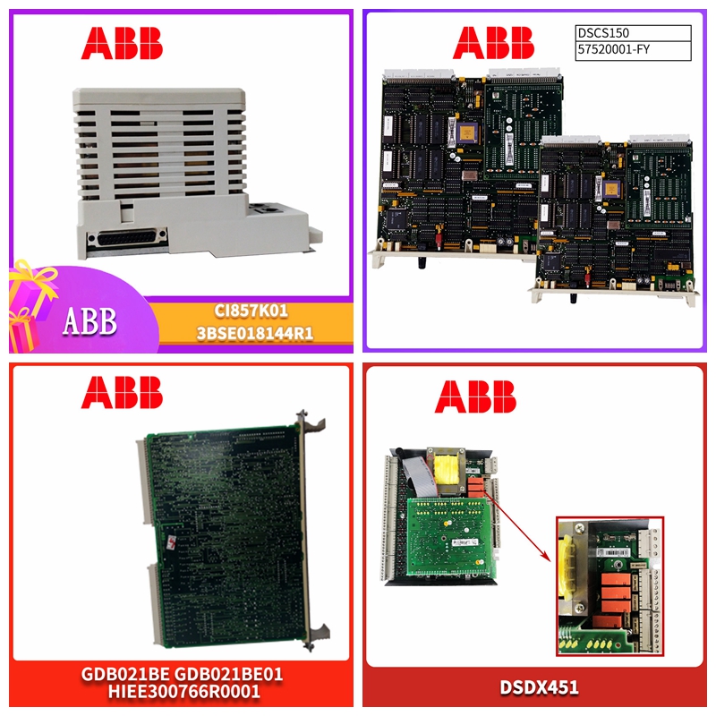
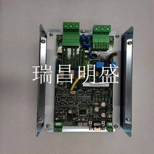
PU519 3BSE018681R1脉冲输入卡件
日期110v 230V 24v勾选框将垫子连接到440F-C28013控制单元图27a终止未使用的垫子连接和连接垫子如果要连接到控制单元的垫子少于8个,则必须使用提供的短路插头终止其他连接。所需的垫子应按顺序(1至8)连接到装置外部的快速连接适配器。如图27a所示,通过断开安装的连接器并更换短路插头来终止未使用的连接器。5.辅助输出:该端子提供适用于指示或报警装置的辅助N/C触点(即,当机器启用灯关闭时闭合)。它们不能连接到安全电路。注:MGCSM1和MGCSM4提供N/C和N/O触点。6.安全输出:这些是用于连接到机器安全电路的无电压端子,即,它们与机器接触器控制电路(最大额定值250V 4A)串联连接。应使用额定值适当的保险丝对其进行外部保护。对于一个接触器,使用连接端子14和23的端子13和24。对于具有两个独立控制电路(即双通道系统)的两个接触器,使用13和14连接连接到一个接触器控制电路,23和24连接到另一个。参见图。14/15和16/17,用于与机器控制电路的典型接口示例。注意:安全输出应通过硬接线直接连接到机器主控制元件(接触器)。它们不得通过任何元件连接,例如普通继电器、PLC等,这些元件未适当指定用于安全相关功能。7.接触器监控:控制单元配有这些连接的端子。当链路被移除时,它们可以连接到机器接触器上的正向导向N/C辅助触点,以监控双通道控制系统中的接触器。如果一个接触器在其控制线圈断电时未能隔离电源,则在故障排除之前,垫控制单元将不允许另一个接触器通电。8.远程复位:N/O-这些端子用于连接远程复位按钮。这必须是一个N/O瞬时按钮装置,其位置应能提供检测区域的全貌。仅限440F-C4000P、440F-C4000 S、440F-C28013。如果从控制单元上看不到危险区域的全貌,请断开接线盒上控制单元盖上的复位开关的电线,以禁用控制单元的复位功能。9.远程复位指示:如果与发光的按钮远程复位开关一起使用,将显示何时需要复位垫子系统。这些端子用于连接灯泡(28V)。32 MAT 1 MAT 2 MAT 3 MAT 4 MAT 5 MAT 6 MAT 7短接插头MAT 8 10.手动复位/自动复位:M/A开关。将M/A开关设置为所需设置。M=手动复位模式A=自动复位模式。11.根据建立的电压和模式设置标记并签署标签。12.标记为1至8的八个六通接头。
Date 110v 230V 24v check box connects the mat to 440F-C28013 control unit Figure 27a Terminate unused mat connection and connecting mat If there are less than 8 mats to be connected to the control unit, other connections must be terminated with the short-circuit plug provided. The required pads shall be connected in sequence (1 to 8) to the quick connect adapters outside the unit. As shown in Figure 27a, terminate the unused connector by disconnecting the installed connector and replacing the short circuit plug. 5. Auxiliary Output: This terminal provides an auxiliary N/C contact for an indication or alarm device (i.e., it closes when the machine enable lamp is turned off). They cannot be connected to safety circuits. Note: MGCSM1 and MGCSM4 provide N/C and N/O contacts. 6. Safe output: These are the voltage free terminals used to connect to the machine safety circuit, that is, they are connected in series with the machine contactor control circuit (maximum rated value 250V 4A). They shall be externally protected by suitably rated fuses. For a contactor, use terminals 13 and 24 that connect terminals 14 and 23. For two contactors with two independent control circuits (i.e. dual channel system), connect to one contactor control circuit using 13 and 14 connections, and connect to the other using 23 and 24 connections. See Fig. 14/15 and 16/17 for typical interface examples with machine control circuits. Note: The safety output should be directly connected to the main control element (contactor) of the machine through hard wiring. They shall not be connected by any element, such as common relays, PLC, etc., which are not properly designated for safety related functions. 7. Contactor monitoring: the control unit is equipped with these connected terminals. When the links are removed, they can be connected to the positive pilot N/C auxiliary contacts on the machine contactors to monitor the contactors in the dual channel control system. If a contactor fails to isolate power when its control coil is powered off, the pad control unit will not allow another contactor to be powered on before troubleshooting. 8. Remote reset: N/O - These terminals are used to connect the remote reset button. This must be a N/O instantaneous button device, whose position should provide a full view of the detection area. Only 440F-C4000P, 440F-C4000 S, 440F-C28,013. If you cannot see the full view of the hazardous area from the control unit, disconnect the wire of the reset switch on the control unit cover on the junction box to disable the reset function of the control unit. 9. Remote reset indication: if it is used together with the illuminated button remote reset switch, it will display when the mat subsystem needs to be reset. These terminals are used to connect bulbs (28V). 32 MAT 1 MAT 2 MAT 3 MAT 4 MAT 5 MAT 6 MAT 7 Short circuit plug MAT 8 10. Manual reset/automatic reset: M/A switch. Set the M/A switch to the desired setting. M=manual reset mode A=automatic reset mode. 11. Set the mark and sign the label according to the established voltage and mode. 12. Eight six way connectors marked 1 to 8.


