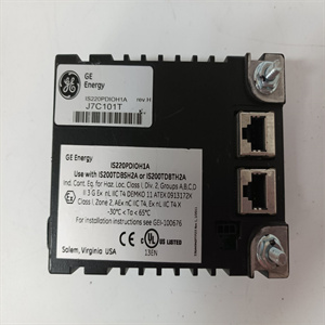
RMP200-8工控机器人备件
起伏、凸起、大间隙或其他不规则现象将增加传感器垫的灵敏度,并可能导致间歇性意外关闭(有害跳闸)。图10垫子的地板状况。可接受小而规则的突起,如棋盘图案。脱脂混凝土地板是理想的。如果有任何疑问,请联系供应商。5.3.7控制单元安装(参考图8第4节)控制单元不得安装在检测区域内。如果手动复位或常规指示器观察需要接近控制单元,则应将其安装在保护区外的可接近位置,以便能很好地观察危险和保护区。复位执行机构应位于保护区外,且位置应确保危险和保护区清晰可见。在其他情况下,考虑到测试和维护的访问要求,控制单元可以安装在保护区外任何方便的地方。440F-C4000D控制单元应安装在防护等级至少为IP 54的外壳内(符合EN 60529)。注意:控制装置不适合直接暴露于高压清洗。5.4垫子定位5.4.1用作组合跳闸和存在感测装置垫子边缘的定位计算为与危险区的水平距离。将危险区域定义为一个体积,考虑到机器的所有可能模式和工件尺寸的所有变化。必须记录危险区域的尺寸和位置以及使用的假设,以便检查防护措施的充分性。如果其他防护措施与垫子系统一起使用,可能会影响确保盖子和格栅与地板表面齐平。无松散碎屑或突起。传感器垫不得下垂或起伏。没有锋利的边缘。传感器垫传感器垫16对垫的尺寸和位置的要求,如图11所示。图11。注意:固定防护装置应符合EN 953、EN 294和EN 811的要求。首先,确定需要穿过垫系统无障碍进入危险区域的路线。考虑所有日常访问需求,如产品检查、机器检查和调整、刀具更换和清除堵塞。还考虑v过程的视觉观察。在干预过程中,考虑机器附近人员和辅助设备的空间要求。安全距离计算对于使用垫子系统作为组合跳闸和存在感测系统的应用,应根据EN999进行计算。图12的流程图显示了基本步骤。注:如果机器的设计符合该机器的现有协调欧洲“C”型标准,该标准给出了具体公式或最小距离,则应优先使用EN 999中给出的公式。传感器垫危险危险传感器垫传感器垫固定防护延伸固定防护箭头显示通道17图12流程图显示方法计算的最小距离是传感器垫检测区外缘到危险最近部分的最小水平距离。地面安装式安全垫的EN 999公式为S=(1600 x T)+1200mm S是最小安全距离,单位为毫米。系数1600是基于进场速度1600mm/S的标准假设。T是以秒为单位的总停止时间。
Fluctuations, bulges, large gaps, or other irregularities will increase the sensitivity of the sensor pads and may cause intermittent accidental shutdowns (harmful trips). Fig. 10 Floor condition of mat. Small and regular protrusions, such as chessboard patterns, are acceptable. Degreasing concrete flooring is ideal. If you have any questions, please contact the supplier. 5.3.7 Installation of control unit (refer to Section 4 of Figure 8) The control unit shall not be installed in the detection area. If manual reset or conventional indicator observation requires access to the control unit, it should be installed in an accessible position outside the protected area so that the danger and protected area can be observed well. The reset actuator shall be located outside the protected area, and the location shall ensure that the danger and the protected area are clearly visible. In other cases, considering the access requirements for testing and maintenance, the control unit can be installed at any convenient place outside the protected area. The 440F-C4000D control unit shall be installed in an enclosure with a degree of protection of at least IP 54 (in accordance with EN 60529). Note: The control device is not suitable for direct exposure to high-pressure cleaning. 5.4 Cushion positioning 5.4.1 The positioning of the edge of the cushion used for combined tripping and presence sensing devices is calculated as the horizontal distance from the hazardous area. The hazardous area is defined as a volume, taking into account all possible modes of the machine and all changes in the size of the workpiece. The size and location of the hazardous area and the assumptions used must be documented in order to check the adequacy of the protective measures. If other protective measures are used together with the mat subsystem, it may affect ensuring that the cover and grille are flush with the floor surface. No loose debris or protrusions. The sensor pad must not sag or fluctuate. No sharp edges. The requirements of sensor pad 16 on the size and position of the pad are shown in Figure 11. Figure 11. Note: The fixed protective device shall comply with the requirements of EN 953, EN 294 and EN 811. First, determine the route that needs to pass through the mat system to enter the hazardous area unobstructed. Consider all daily access needs, such as product inspection, machine inspection and adjustment, tool replacement, and removal of blockages. Visual observation of v process is also considered. During the intervention, consider the space requirements for personnel and auxiliary equipment near the machine. Safety distance calculation For applications using the mat subsystem as a combined trip and presence sensing system, it shall be calculated according to EN999. The flowchart in Figure 12 shows the basic steps. Note: If the design of the machine complies with the existing harmonized European "C" standard for the machine, which gives a specific formula or a minimum distance, the formula given in EN 999 shall prevail. Sensor pad Hazard sensor pad Sensor pad Fixed protection Extended fixed protection arrow Display channel 17 Figure 12 Flow chart Display method The minimum distance calculated by the display method is the minimum horizontal distance from the outer edge of the sensor pad detection area to the nearest part of the hazard. The EN 999 formula of ground mounted safety pad is S=(1600 x T)+1200mm S is the minimum safety distance, and the unit is mm. The coefficient 1600 is a standard assumption based on the approach speed of 1600mm/S. T is the total stop time in seconds.


