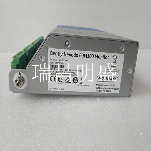
U70 3BHB006208R0001工控备件机器人模块
控制引脚
可以外部驱动,使用跳线设置为高或低,或使用微控制器连接时进行控制。上包括电平移位缓冲器,因此可以控制到的信号,同时支持和保持从到的整个电压和逻辑电平范围。用于电源连接的转塔的更多功能位于板的右边缘。如果与一起使用,这些连接是可选的。上总线引脚的测试点和接线板连接位于板的右边缘。逻辑电平信号的测试点和跳线位于电路板的左侧边缘。绿色指示数据输入存在低电压。黄色指示接收器输出低。
在没有驱动信号
跳线的情况下,所有逻辑引脚上的个上拉或下拉电阻器提供定义的逻辑状态。板左下角附近的四个开关可用于为板提供可访问的唯一地址,允许代码支持多个板,唯一地址。操作启用单通道驱动器和接收器或一个驱动器和一个接收器,可通过控制引脚进行选择。在模式低下,驱动器和接收器始终处于活动状态,可实现高达的快速模式。在模式高下,驱动器和接收器仅在其相关的使能引脚和分别被驱动为高电平和低电平时才激活。
.Control pin
It can be externally driven, set to high or low using jumpers, or controlled when connected using a microcontroller. The upper part includes a level shift buffer, so the signal to can be controlled, and the entire voltage and logic level range from to can be supported and maintained at the same time. More functions of the turret for power connection are located on the right edge of the board. These connections are optional if used with. The test point of the upper bus pin and the terminal block connection are located on the right edge of the board. The test point and jumper of logic level signal are located on the left edge of the circuit board. Green indicates that low voltage is present at the data input. Yellow indicates low receiver output.
When there is no drive signal
In the case of jumpers, pull-up or pull-down resistors on all logic pins provide a defined logic state. The four switches near the lower left corner of the board can be used to provide a unique accessible address for the board, allowing the code to support multiple boards with unique addresses. Operation enables single channel driver and receiver or one driver and one receiver, which can be selected through the control pin. In low mode, the driver and receiver are always active, which can achieve up to fast mode. In mode high, the driver and receiver are only activated when their associated enable pins and are driven to high and low levels respectively.


