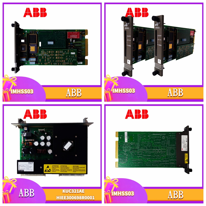
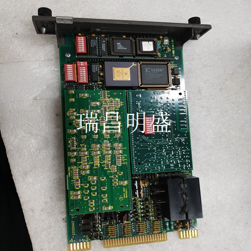
UFC760BE142 3BHE004573R0142工控模块卡件
17以太网端口
1(3)(RJ45)9电源输入,AC 6421 7 53 16 15 14 12 11 13 10 9 8 17紧凑型工业非显示计算机7自动化出版物6155RIN002EENP2013年7月计算机安装需要这些工具:•2号十字螺丝刀•钻头电机和钻头•防静电腕带(推荐)安装间隙检查计算机尺寸,确保允许计算机周围的通风和电缆连接间隙。安装在机柜或高温区域时,计算机周围的环境温度不得超过工作温度范围。对于25 mm(1 in.)的计算机侧面,使用该间隙51 mm(2 in.)计算机顶部13 mm(0.5 in.)(1)(1。电脑底部无电脑后部有足够的间隙,以容纳超出手柄的电缆。计算机正面8紧凑型工业非显示计算机自动化出版物6155RIN002EENP2013年7月安装计算机计算机支持各种安装选项:•壁装•DIN导轨安装•VESA安装每个安装选项都配有带安装螺钉的支架。将计算机安装在墙上您可以使用安装支架将计算机安装到墙上。壁装支架尺寸见第11页。
计算机安装到墙上
1.在墙上钻四个M4孔,最小5 mm,与安装支架上的孔相对应。2.将安装支架连接到计算机的底部或背面(1)。3.用提供的M4 x 8 mm盘头螺钉(2)固定安装支架。将螺钉拧紧至0.686 N•m(6.072 lb•in)。4.将计算机靠在墙上,将安装支架上的孔与墙上的孔对齐(3)。提示:用搁板或其他方式支撑计算机,以便于在适当的高度安装。底部紧凑型工业非显示计算机背面安装支架上的安装支架9自动化出版物6155RIN002EENP2013年7月5。将剩余的M4平头螺钉穿过安装支架插入墙壁并拧紧(4)。
17 Ethernet port
1 (3) (RJ45) 9 Power input, AC 6421 7 53 16 15 14 11 13 10 9 17 Compact industrial non display computer 7 Automation publication 6155RIN002EENP July 2013 Computer installation requires these tools: • # 2 Phillips screwdriver • Drill motor and drill bit • Anti static wrist strap (recommended) Installation clearance Check the computer size to ensure that ventilation and cable connection clearance around the computer are allowed. When installed in the cabinet or high temperature area, the ambient temperature around the computer shall not exceed the operating temperature range. For the 25 mm (1 in.) side of the computer, use the gap of 51 mm (2 in.) for the top 13 mm (0.5 in.) of the computer )(1) (1) There is not enough space at the bottom of the computer. There is enough space at the back of the computer to accommodate cables beyond the handle. Front of the computer 8 Compact industrial non display computer automation publication 6155RIN002EENP July 2013 Installation of the computer The computer supports various installation options: • Wall mounting • DIN rail mounting • VESA installation Each installation option comes with a bracket with mounting screws. Installing the computer on the wall You can use the mounting bracket to install the computer To the wall. See page 11 for wall mounting bracket dimensions.
Computer mounted on the wall
1. Drill four M4 holes on the wall, minimum 5 mm, corresponding to the holes on the mounting bracket. 2. Connect the mounting bracket to the bottom or back of the computer (1). 3. Fix the mounting bracket with the M4 x 8 mm pan head screws (2) provided. Tighten the screws to 0.686 N • m (6.072 lb • in). 4. Place the computer against the wall and align the holes on the mounting bracket with the holes on the wall (3). Tip: Support the computer with shelves or other means to facilitate installation at an appropriate height. Mounting bracket 9 on the back mounting bracket of the bottom compact industrial non display computer Automation publication 6155RIN002EENP July 5, 2013. Insert the remaining M4 pan head screws through the mounting bracket into the wall and tighten (4).


