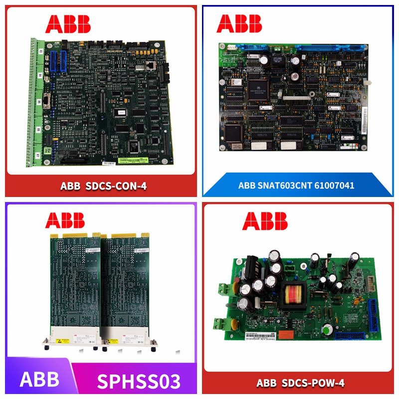
XVC768AE105 3BHB007211R0105自动化模块
如果寄存器设置为低
(默认值),也可用于读取数据。数据表版|,共,引脚号记忆描述芯片选择条。用于激活上的端口,处于低电平激活状态。当变高时,先前计时到移位寄存器的数据被锁存到芯片。将Ω的上拉电阻器连接到的.,以确保接口在不使用时停用。串行数据输出。如果寄存器,位设置为高,则可以在线上读回寄存器状态。差分输出。±为Ω差分对,内部交流耦合。±工作频率为至。所有八条线路的电气和机械长度必须相等。外露衬垫。暴露的焊盘必须连接到具有低热阻和电阻抗的接地平面。数据表版|,共典型性能特性()输出频率电源电流()与输出频率和温度,电源电压=.功耗与输出频率和温度,电源电压=.输出频率
主要元件.
是一个输入缓冲器、一个带集成可切换谐波滤波器的倍倍频器、一个信号分离器和四个差分输出,它们可以驱动具有差分输入的偶极子或类似天线。施加.和之间的输入信号,功率电平约为−到端口(引脚),这导致每个差分输出±(引脚、引脚、引脚、引脚、引脚、引脚、引脚和引脚)上的标称输出功率为。这些子电路的操作可以通过端口以及两个可编程状态机来控制,一个专注于乘法器滤波器控制,另一个关注于传输控制。
If the register is set to low
(default) can also be used to read data. Data sheet version |, total, pin number memory description chip selection bar. Used to activate the port on, which is in the low level active state. When it becomes high, the data previously timed to the shift register is locked to the chip. Connect the pull-up resistor of Ω to the, To ensure that the interface is deactivated when not in use. Serial data output. If the register bit is set to high, the register status can be read back online. Differential output. ± is an Ω differential pair with internal AC coupling. ± Operating frequency is to. All eight lines must have equal electrical and mechanical lengths. Exposed gaskets. Exposed pads must be connected to a ground plane with low thermal resistance and impedance. Data sheet version |, a total of typical performance characteristics () Output frequency Power supply current () and output frequency and temperature, power supply voltage=. Power consumption and output frequency and temperature, power supply voltage=. Output frequency
Main components
It is an input buffer, a frequency multiplier with integrated switchable harmonic filter, a signal separator and four differential outputs, which can drive dipoles or similar antennas with differential inputs. exert. For the input signal between and, the power level is about − to the port (pin), which results in the nominal output power on each differential output ± (pin, pin, pin, pin, pin, pin and pin) being. The operation of these sub circuits can be controlled through ports and two programmable state machines, one focusing on multiplier filter control and the other on transmission control.


