


A4H124-24FX P0973JN 24端口光纤管理交换机
将Lexan防护罩更换到隔离板上
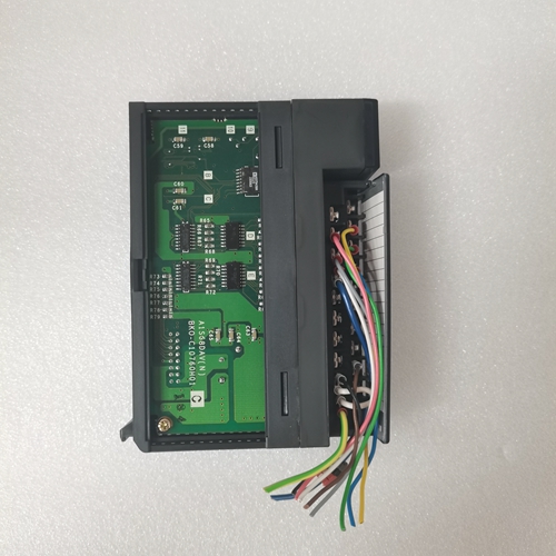
验证SW1设置正确(115V AC)。结束步骤安装隔离板后,更换所有Lexan屏蔽并固定隔间门。将电路板送至自动化公司进行维修,或根据贵公司的程序和当地条例处理旧电路板!注意:SW1必须设置为适当的控制功率。将SW1设置为错误设置将导致隔离板和其他部件损坏。出版物2364F-5.13 1999年6月PN 192666取代出版物2364F-5.13 1999 1999年3月版权所有1999年国际公司。在美国印刷的Lexan是General Electric Corporation的商标请确认您已收到出版物2364F-5.13 1999年6月更换套件说明RGU中的相应项目™ 隔离板更换内容本文档介绍了如何拆卸和更换再生直流母线电源装置(RGU)中的隔离板和负载电阻器。此工具包包含的内容使用下表,验证您已收到工具包中的相应项目。
如果您收到了隔离板套件:
如果您收到负载电阻器套件:注意:请参阅表a以验证您是否收到了适当的负载电阻器套件。需要的其他项目在开始之前,请确保您还拥有以下工具:•您需要的工具:–测量电压–拆卸、松开和拧紧螺钉(包括端子螺钉)–拧紧螺钉(6 lb in/0.7 N-m)•文档:–您的驱动系统示意图–出版物2364F-5.01,再生直流母线电源装置(RGU)-用户手册注意:如果现有负载电阻器损坏,您需要订购适当的电阻器套件(参见第4页的表A)。对于此部件:您应收到此数量:隔离板1 ESD腕带1对于此部件,您应收到以下数量:负载电阻器2(对于A系列RGU)3(对于B系列RGU,)出版物2364F-5.13 1999年6月2 RGU™ 隔离板更换安全预防措施在维修RGU或驱动系统时,以下一般预防措施适用:特殊说明重要:您需要重新使用从装置上拆下的部件。将零件按拆下的顺序放在干净的表面上!
Replace the Lexan shield to the isolation panel
Verify that SW1 is set correctly (115V AC). At the end of the step, replace all Lexan shields and secure the compartment door after installing the isolation panel. Send the circuit board to the automation company for maintenance, or dispose of the old circuit board according to your company's procedures and local regulations! Note: SW1 must be set to the appropriate control power. Setting SW1 to the wrong setting will cause damage to the isolation panel and other components. Publication 2364F-5.13 June 1999 PN 192666 replaces publication 2364F-5.13 March 1999 Copyright 1999 International Corporation. Lexan printed in the United States is a trademark of General Electric Corporation. Please confirm that you have received the corresponding item in publication 2364F-5.13, June 1999 Replacement Kit Instructions RGU ™ Isolation board replacement content This document describes how to remove and replace the isolation board and load resistor in the regenerative DC bus power supply unit (RGU). Use the following table to verify that you have received the corresponding items in the toolkit.
If you received a closeout kit:
If you have received a load resistor kit: Note: Refer to Table a to verify that you have received the appropriate load resistor kit. Other items required Before starting, please ensure that you also have the following tools: • Tools you need: – Measuring voltage – Removing, loosening and tightening screws (including terminal screws) – Tightening screws (6 lb in/0.7 N-m) • Documents: – Schematic diagram of your drive system – Publication 2364F-5.01, Regenerative DC bus power supply unit (RGU) - User's manual Note: If the existing load resistor is damaged, You need to order the appropriate resistor kit (see Table A on page 4). For this part: you should receive this quantity: isolation board 1 ESD wrist strap 1 For this part, you should receive the following quantity: load resistor 2 (for A series RGUs) 3 (for B series RGUs) publication 2364F-5.13 June 1999 2 RGUs ™ Safety precautions for the replacement of isolation plate When repairing the RGU or drive system, the following general precautions apply: Special instructions Important: You need to reuse the parts removed from the device. Place the parts on a clean surface in the order they were removed!
")
")
")

