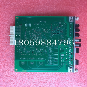
3BHE019633R0101模块备件
电机电枢电流
使用表A中提供的信息,验证是否为您的应用选择了合适的凸耳套件。表A接线片套件规格额定电机电枢电流(1)A直流接触器额定值A直流电枢导线尺寸(2)mm2(AWG)DB导线尺寸(3)mm2(DWG)电枢导体压接接线片孔尺寸mm(in.)DB导线压接接线孔尺寸mm。)吊耳套件目录号是电枢导线尺寸(第3列)和直流接触器额定值(第2列)允许的最大电流。(2) 根据NEC 430-22(1987)的规定,电枢导体的尺寸是将额定电机电枢电流乘以1.25。直流接线片额定值根据NEC表310-16(1987)确定,铜导体的绝缘温度为75°C(167°F),环境温度为30°C(86°F)。如果条件不是NEC表310-16所示,则参考适用规范。(3) 动态制动(DB)导线的尺寸如注2所示,但由于这些导线中的电流持续时间较短,因此电流为半安培,且其尺寸符合NEMA标准ICS 3-302.62-动态制动。
负载惯性大于电机
如果负载惯性大于电机的惯性,则必须根据NEMA标准ICS 3.302.62进行计算,以确定正确的导体尺寸和DB电阻器瓦特数。出版物1370-IN011B-EN-P 1370直流回路接触器和接线片套件7。以下程序描述了正确安装接线片所需的步骤。推荐的压缩工具是Thomas&Betts Corporation压缩工具型号TBM6或TBM6S。1.确保驱动器的电源已断开。2.仔细准备UL认证或认可和/或CSA认证电线的端部,安装适当的接线片和压接。对其余接线片/导线重复上述步骤。3.使用接触器随附的螺钉/螺栓,将接线片连接到适当的端子上。
Motor armature current
Using the information provided in Table A, verify that the appropriate lug kit is selected for your application. Table A Specification of lug kit Rated motor armature current (1) A DC contactor rating A DC armature wire size (2) mm2 (AWG) DB wire size (3) mm2 (DWG) Armature conductor crimping lug hole size mm (in.) DB wire crimping hole size mm.) The lug kit catalog number is the maximum current allowed by the armature conductor size (column 3) and the DC contactor rating (column 2). (2) According to NEC 430-22 (1987), the size of armature conductor is the rated motor armature current multiplied by 1.25. The DC lug rating is determined according to NEC Table 310-16 (1987). The insulation temperature of copper conductor is 75 ° C (167 ° F), and the ambient temperature is 30 ° C (86 ° F). If the conditions are not shown in NEC Table 310-16, refer to the applicable code. (3) The dimensions of dynamic braking (DB) conductors are shown in Note 2. However, due to the short duration of the current in these conductors, the current is half an ampere, and their dimensions comply with NEMA standard ICS 3-302.62 - dynamic braking.
Load inertia is greater than motor
If the load inertia is greater than the motor inertia, it must be calculated according to NEMA standard ICS 3.302.62 to determine the correct conductor size and DB resistor wattage. Publication 1370-IN011B-EN-P 1370 DC Loop Contactor and Lug Kit 7. The following procedure describes the steps required to properly install the lug. The recommended compression tool is Thomas&Betts Corporation compression tool model TBM6 or TBM6S. 1. Make sure the power to the drive is disconnected. 2. Carefully prepare the ends of UL certified or approved and/or CSA certified wires, and install appropriate lugs and crimps. Repeat for the remaining lugs/wires. 3. Connect the lug to the appropriate terminal using the screws/bolts supplied with the contactor.


