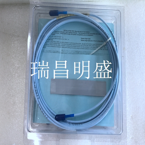
330130-045-00-00延伸线缆
机架接口模块使用两种I/O模块类型
即机架接口I/O模块和数据管理器I/O模块。这些I/O模块允许您将3301主机和通信处理器(TDIX或DDIX)连接到3301机架,并将菊花链机架连接在一起。本节介绍如何使用I/O模块上的连接器,列出要使用的电缆,并显示电缆的引脚。一次只能将一个机架接口输入/输出模块安装在机架接口模块后面(机架安装或面板安装机架中)或机架接口模块上方(隔板机架中)。另请参见第4.1节,一个Data Manager I/O模块可以安装在电源输入模块和机架接口I/O模块之间(在机架安装或面板安装机架中),或者安装在电源模块和机架界面I/O模块之间的电源上方(在隔板机架中)。参见第4.2节4输入/输出模块说明3301/20操作和维护16 4.1机架接口输入/输出(I/O)模块。可用于3301监控系统的两种机架接口I/O模块是RS-232/RS-422 I/O模块和调制解调器I/O模块。以下功能对两个I/O模块都是通用的。机架接口输入/输出模块必须安装在机架接口模块后面(机架安装或面板安装机架中)或机架接口模块上方(隔板机架中)。1)
正常继电器:
正常继电器正常通电,用于指示3301监测系统是否正常。2)机架RS-422:用于菊花链连接下一个3301机架。最多12个机架可以菊花链连接在一起。此连接只能使用RS-422。3) 外部触点:•跳闸倍增•机架报警抑制•机架复位3301/20操作和维护4输入/输出模块说明17 OK继电器以下项目将导致OK继电器不正常:•从3301机架上拆除机架接口模块•将模块插入3301机架(自检期间)•传感器不正常(键相器除外)•内部硬件故障a模块•配置故障•插槽ID故障•3301机架中检测到故障的任何模块下图显示了正常继电器的不同接线方式:正常通电无电源/有电源/(机框状态)正常状态不正常状态No表示常开。ARM指电枢。NC表示常闭。RACK RS-422用于菊花链连接到链中的下一个3301机架。电缆将连接到此机架上的机架RS-422连接器和下一个3301机架上的主机连接器之间。此连接只能使用RS-422。参考第4.1.2节外部触点这些需要干触点输入。要启用特定功能,请将所需触点短接到系统公用线(COM)。跳闸倍增(TM)用于在机架应处于跳闸倍增状态时发出信号。
The Rack Interface Module uses two I/O module types
The rack interface I/O module and the data manager I/O module. These I/O modules allow you to connect a 3301 host and communication processor (TDIX or DDIX) to a 3301 rack and connect daisy chain racks together. This section describes how to use the connectors on the I/O module, lists the cables to be used, and displays the pins of the cables. Only one Rack Interface I/O Module can be installed behind a Rack Interface Module (in a rack mounted or panel mounted rack) or above a Rack Interface Module (in a bulkhead rack) at a time. Also see section 4.1, a Data Manager I/O module can be installed between the power input module and the rack interface I/O module (in a rack mounted or panel mounted rack), or above the power supply between the power module and the rack interface I/O module (in a bulkhead rack). Refer to Section 4.2 4 I/O Module Description 3301/20 Operation and Maintenance 16 4.1 Rack Interface I/O Module. The two types of rack interface I/O modules available for the 3301 monitoring system are RS-232/RS-422 I/O modules and modem I/O modules. The following functions are common to both I/O modules. The Rack Interface I/O Module must be installed behind the Rack Interface Module (in a rack mounted or panel mounted rack) or above the Rack Interface Module (in a bulkhead rack). 1)
Normal relay:
The normal relay is normally energized to indicate whether the 3301 monitoring system is normal. 2) Rack RS-422: used to connect the next 3301 rack with daisy chain. Up to 12 racks can be daisy chained together. This connection can only use RS-422. 3) External contacts: • Trip Multiplier • Rack Alarm Inhibit • Rack Reset 3301/20 Operation and Maintenance 4 I/O Module Description 17 OK Relay The following items will cause the OK relay to malfunction: • Remove the Rack Interface Module from the 3301 rack • Insert the module into the 3301 rack (during self-test) • The sensor is not OK (except for the Keyphasor) • Internal hardware failure a module • Configuration failure • Slot ID failure • Any module with failure detected in the 3301 rack The following figure shows the different wiring methods of the normal relay: normally powered on without power supply/with power supply/(rack status) normal status abnormal status No means normally open. ARM refers to the armature. NC means normally closed. RACK RS-422 is used for daisy chain connection to the next 3301 rack in the chain. The cable connects between the rack RS-422 connector on this rack and the host connector on the next 3301 rack. This connection can only use RS-422. Refer to Section 4.1.2 External Contacts These require dry contact inputs. To enable a specific function, short the desired contact to the system common (COM). Trip Multiplier (TM) is used to signal when the rack should be in Trip Multiplier status.


