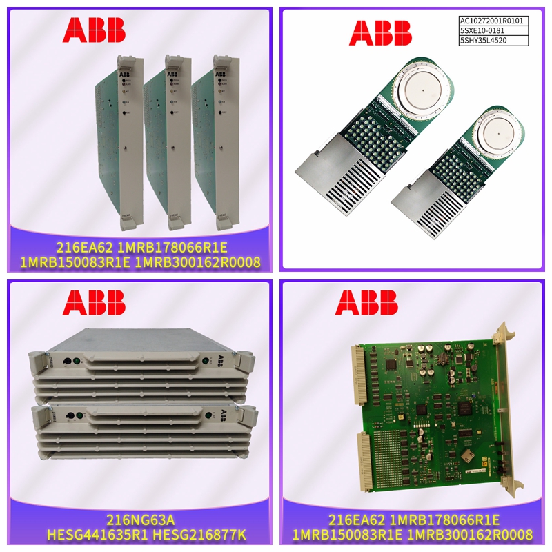
1440-DYN02-01RJ PLC模块控制器
低报警触点
PLC还使用此信息驱动与一些模拟输入相关的任何高和低报警触点。每个离散输入位都有一个位点故障触点。每个模拟输入通道都有一个包含点故障和报警故障触点的单字节。FIP总线控制器将成功使用的验证器TVA放置在该区域,无需修改。如果无法使用验证器TVA,通常是由于缺乏及时性或刷新,FBC仅设置影响离散和模拟数据点故障触点的位。模拟TVA的剩余位保持其最后状态。因此,如果设置了任何报警接触位,则如果验证器TVA不能再使用,则保持设置。FBC存储器的离散和模拟输出数据区域FBC存储器中的该区域包含每个配置的输出应用程序传输变量(TVA)。CPU将输出数据(包括PLC的%Q和%AQ参考表中的状态和闪烁数据)放入该区域。当FBC检测到新的输出数据时,它将数据直接复制到一个或多个COMV中,并在FIP网络上生成每个COMV。如果FIP总线控制器未从PLC CPU接收到新数据,则不会刷新COMV。然后,基于配置的刷新定时器,COMV可以变为未刷新。4 4-4系列90-70 FIP总线控制器用户手册–1997年11月GFK-1038A FIP总线总线控制器I/O扫描FIP总线处理器扫描FIP网络的I/O数据。在FIP网络上,每个I/O数据TVA都分配给一个时隙。时隙时隙是FIP宏周期中在指定时间段发生的特定段。在PLC CPU中,每个时隙必须与其中一个CPU扫描集相关联。一个或多个时隙可以包括在同一扫描集中。在FIP网络上,分配给同一时隙的I/O数据TVA被组合成通信变量(COMV)。然后,COMV在为TVA定义的同一时隙内在FIP网络上传输。异步或同步网络访问FBC提供两种网络访问方法,异步和同步。使用哪种方法取决于PLC应用程序的需要。
生产同步
如果应用程序必须与FIP网络上数据的实际生产同步,则必须使用同步扫描方法。在所有其他情况下,异步网络访问方法可能更可取。默认网络设置默认情况下,网络访问方法为异步。在异步模式下,所有I/O数据仍连接到时隙,但FIP总线控制器与网络上数据的实际生产和消耗不同步。传输时隙默认值下表列出了传输时隙的默认设置。有关传输时隙的更多详细信息,请参见第3章。网络访问:异步FIP宏周期持续时间:150mS时隙名称周期描述DI 50ms C 4 GFK-1038A第4章操作4-5异步I/O扫描异步输入扫描在异步I/O扫描模式下,FIP总线控制器在网络上产生的输入数据期间扫描来自FIP网络的输入数据,但是异步的。这意味着FBC消耗来自网络的数据,而不考虑数据出现在网络上的实际时刻。因此,提供给CPU的数据可能是在网络上的不同时间产生的。如果一个时隙中的所有数据都必须是一致的,那么应该设置同步操作。在异步I/O扫描模式下,FIP总线控制器在指定时间段连续扫描输入数据,并使数据可供CPU使用。CPU根据扫描集的要求扫描来自FBC的输入数据,例如每次扫描、每5次扫描等。异步输出扫描FIP总线控制器仅在CPU执行包含时隙的扫描集的输出扫描时刷新时隙中的输出数据。因此,如果CPU延迟第一次输出扫描,FBC的输出数据将具有不重要的状态。一旦CPU执行输出扫描,FBC将刷新该时隙的输出数据。
Low alarm contact
The PLC also uses this information to drive any high and low alarm contacts associated with some analog inputs. Each discrete input bit has a bit fault contact. Each analog input channel has a single byte containing point fault and alarm fault contacts. The FIP bus controller places the successfully used verifier TVA in this area without modification. If the verifier TVA cannot be used, usually due to the lack of timeliness or refresh, the FBC only sets the bits that affect the discrete and analog data point fault contacts. The remaining bits of the analog TVA remain in their last state. Therefore, if any alarm contact bit is set, if the verifier TVA can no longer be used, it remains set. Discrete and analog output data area of the FBC memory This area in the FBC memory contains output application transfer variables (TVA) for each configuration. The CPU places output data (including status and flicker data in the PLC's% Q and% AQ reference tables) in this area. When FBC detects new output data, it directly copies the data to one or more COMVs, and generates each COMV on the FIP network. If the FIP Bus Controller does not receive new data from the PLC CPU, the COMV is not refreshed. Then, based on the configured refresh timer, the COMV can become not refreshed. 4 4-4 Series 90-70 FIP Bus Controller User's Manual – November 1997 GFK-1038A FIP Bus Controller I/O Scan FIP Bus Processor scans the I/O data of the FIP network. On the FIP network, each I/O data TVA is allocated to a time slot. Time slot A time slot is a specific segment of the FIP macro cycle that occurs in a specified time period. In the PLC CPU, each time slot must be associated with one of the CPU scan sets. One or more time slots may be included in the same scan set. On the FIP network, the I/O data TVA allocated to the same time slot is combined into a communication variable (COMV). Then, COMV transmits on the FIP network in the same time slot defined for TVA. Asynchronous or synchronous network access FBC provides two network access methods, asynchronous and synchronous. Which method to use depends on the needs of the PLC application.
Production synchronization
If the application must synchronize with the actual production of data on the FIP network, the synchronous scanning method must be used. In all other cases, asynchronous network access may be preferable. Default Network Settings By default, the network access method is asynchronous. In asynchronous mode, all I/O data is still connected to time slots, but the FIP bus controller is not synchronized with the actual production and consumption of data on the network. The following table lists the default settings of transmission timeslots. For more details on transmission timeslots, see Chapter 3. Network access: asynchronous FIP macro cycle duration: 150mS slot name cycle description DI 50ms C 4 GFK-1038A Chapter 4 Operation 4-5 Asynchronous I/O scanning Asynchronous input scanning In the asynchronous I/O scanning mode, the FIP bus controller scans the input data from the FIP network during the input data generated on the network, but asynchronously. This means that FBC consumes data from the network, regardless of the actual time when the data appears on the network. Therefore, the data provided to the CPU may be generated at different times on the network. If all the data in a time slot must be consistent, the synchronization operation should be set. In the asynchronous I/O scan mode, the FIP Bus Controller continuously scans the input data during a specified period of time and makes the data available to the CPU. The CPU scans the input data from the FBC according to the requirements of the scan set, such as every scan, every 5 scans, etc. The asynchronous output scan FIP bus controller refreshes the output data in the timeslot only when the CPU performs an output scan of the scan set containing the timeslot. Therefore, if the CPU delays the first output scan, the output data of the FBC will have an unimportant state. Once the CPU performs the output scan, the FBC will refresh the output data of the time slot.


