


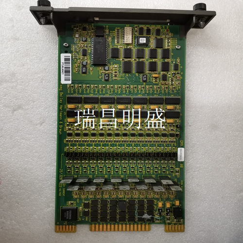
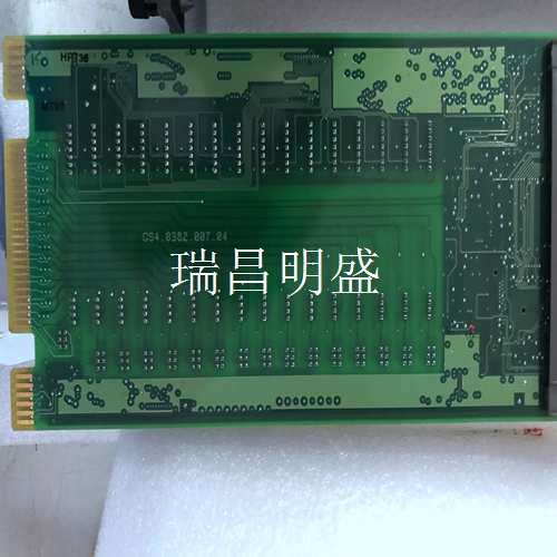
DSMD113 5736045-N 输出输入模块
配置冗余块
兼容性_此模块与型手持式监视器完全兼容。可与IC66*HHM500一起使用;然而,需要HHM501来改变波特率或配置冗余块。如果该块将用于由IC550系列PLC控制的总线或配备总线接口模块的主机上,并且该块将被配置为仅输入块,则可能需要升级IC550总线控制器或计算机总线接口模块,详见《离散和模拟块用户手册》。模块IC66*BBD101设计用于控制小负载,无需增加并联负载电阻。它也适用于工厂互助社要求1级2级额定值的安装。该块与块IC66*CBD100和BBD100向后兼容,可用于替换它们。电子组件IC66*EBD101取代IC66*ELD100和EBD100。端子组件IC66*TSD100E和更高版本与电子组件的早期版本不兼容。如果端子组件将用于更换端子组件IC66*TSD100D或更早版本,则电子组件必须更换为IC66*EBD101F或更高版本,或进行升级。安装说明仔细检查所有装运集装箱是否损坏。如果任何设备损坏,请立即通知送货服务。保存损坏的运输集装箱,以供送货服务部门检查。设备开箱后,记录所有序列号。保存装运集装箱和包装材料,以防需要运输或装运系统的任何部分。块安装Genius I/O块被视为“开放设备”,因此必须安装在保护外壳内。它们应位于清洁且无空气污染物的区域。应有足够的冷却气流。该块可以安装在正上方,也可以倒置。在块之间留出至少2英寸的空间。通过为8-32硬件钻两个螺钉或螺栓孔来安装缸体。定位块,使上下法兰上的槽口与安装孔对齐。使用8-32个螺钉安装块。使用星形垫圈提供接地完整性。拆卸电子组件块的电子组件可更换为兼容型号,无需拆卸现场接线或重新配置块。端子组件固定螺钉(数量2)电子组件连接器引脚1.拧下块顶部和底部的固定螺钉。2.使用块拉拔器(IC660BLM507),将凸耳接合在第一个通风槽中。将工具移动到块的中心并挤压手柄。
向上拉动电子组件
警告:如果现场端子通电,端子组件底部的连接器引脚也会暴露电源,存在触电危险。请勿接触接头针脚!可能导致死亡或受伤。插入电子组件1.将电子组件对准导轨并用力向下推。注意不要用力过猛;它可能会损坏块。2.如果遇到异常电阻,拆下电子组件。如果模块通电,请勿触摸连接器插脚!检查端子组件、连接器插座和连接器边缘板(在电子组件上)。确保键匹配。清除所有障碍物并重新插入电子组件。密切注意导销的对准。3.用端子组件顶部和底部的螺钉固定电子组件。接地块的安装螺钉不得用作块接地的唯一方式。使用最小尺寸AWG#12(横截面平均3.3mm2)的短导线将块上的绿色接地螺钉连接到可靠的接地系统。警告:如果安装螺钉没有良好的接地连接,并且接地螺钉没有连接到可靠的接地,则块没有接地。存在触电危险。可能导致死亡或人身伤害。块接线_所有端子接受一根AWG#12导线(平均横截面为3.3mm2)或两根AWG#14导线(每个平均横截面2.1mm2)。建议的最小导线尺寸为AWG#22(横截面平均36mm2)。块状端子还可容纳宽达0.27英寸(6.85mm)的铲形或环形端子,6号螺钉的最小开口,从螺钉中心到后挡板的深度可达0.20英寸(5.1mm)。确保非屏蔽线端不超过2英寸(5厘米)。不要过度拧紧端子螺钉。所有端子的推荐扭矩为6 in/lb(.678 N/M)。
Configuring Redundant Blocks
Compatibility_ This module is fully compatible with the Type A handheld monitor. It can be used together with IC66 * HHM500; However, HHM501 is required to change the baud rate or configure redundant blocks. If this block is to be used on a bus controlled by an IC550 series PLC or a host equipped with a bus interface module, and this block will be configured as an input block only, it may be necessary to upgrade the IC550 bus controller or computer bus interface module, as detailed in the Discrete and Analog Block User's Manual. The module IC66 * BBD101 is designed to control small loads without increasing the parallel load resistance. It is also suitable for installations requiring Class 1 and Class 2 ratings as required by Factory Mutual. This block is backward compatible with blocks IC66 * CBD100 and BBD100 and can be used to replace them. Electronic components IC66 * EBD101 replace IC66 * ELD100 and EBD100. Terminal assembly IC66 * TSD100E and later versions are incompatible with earlier versions of electronic assemblies. If the terminal assembly will be used to replace the terminal assembly IC66 * TSD100D or earlier, the electronic assembly must be replaced with IC66 * EBD101F or later, or upgraded. Installation instructions Carefully check all shipping containers for damage. If any equipment is damaged, please inform the delivery service immediately. Keep the damaged shipping container for inspection by the delivery service department. After unpacking the equipment, record all serial numbers. Keep shipping containers and packaging materials in case any part of the transportation or shipping system is required. Block mount Genius I/O blocks are considered "open devices" and must therefore be installed in a protective enclosure. They shall be located in a clean area free from air pollutants. There shall be sufficient cooling air flow. The block can be installed directly above or upside down. Leave at least 2 inches of space between the blocks. Install the cylinder block by drilling two screw or bolt holes for the 8-32 hardware. Position the block so that the notches on the upper and lower flanges are aligned with the mounting holes. Use 8-32 screws to install the block. Use star washers to provide ground integrity. The electronic components removed from the electronic module block can be replaced with compatible models without removing the field wiring or reconfiguring the block. Terminal assembly fixing screws (Qty. 2) Electronic assembly connector pin 1. Unscrew the fixing screws at the top and bottom of the block. 2. Use the block puller (IC660BLM507) to engage the lug in the first ventilation slot. Move the tool to the center of the block and squeeze the handle.
Pull the electronics assembly up
Warning: If the field terminal is powered on, the connector pin at the bottom of the terminal assembly will also expose the power supply, which may cause electric shock. Do not touch the connector pins! May cause death or injury. Insert the electronic assembly 1. Align the electronic assembly with the guide rail and push down firmly. Be careful not to exert too much force; It may damage the block. 2. If abnormal resistance is encountered, remove the electronic components. If the module is powered, do not touch the connector pins! Check the terminal assembly, connector socket and connector edge plate (on the electronic assembly). Make sure the keys match. Remove all obstacles and reinsert the electronic components. Pay close attention to the alignment of the guide pins. 3. Fix the electronic components with the screws at the top and bottom of the terminal assembly. The mounting screws of the grounding block shall not be used as the only way to ground the block. Connect the green grounding screw on the block to the reliable grounding system with a short conductor with the minimum size of AWG # 12 (average cross section 3.3mm2). Warning: If the mounting screw is not well grounded and the grounding screw is not connected to a reliable grounding, the block is not grounded. There is a danger of electric shock. May cause death or personal injury. Block wiring_ All terminals accept one AWG # 12 conductor (average cross section 3.3mm2) or two AWG # 14 conductors (average cross section 2.1mm2 each). The recommended minimum conductor size is AWG # 22 (average cross-section of 36mm2). The block terminal can also accommodate spade or ring terminals up to 0.27 inch (6.85 mm) wide. The minimum opening of No. 6 screw can reach 0.20 inch (5.1 mm) deep from the screw center to the tailgate. Ensure that the unshielded wire end does not exceed 2 inches (5 cm). Do not over tighten the terminal screws. The recommended torque for all terminals is 6 in/lb (. 678 N/M).
")
")
")

