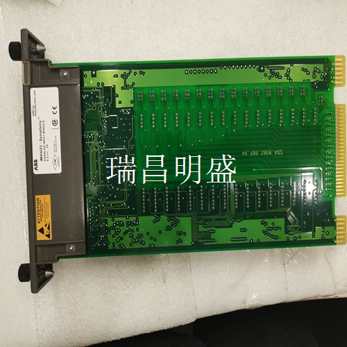
DSDO110 57160001-K 工控模块备件
用单个测压元件测量
力计算在某些情况下,只需在轧辊一端安装一个测压元件即可测量张力。然而,辊的两端都应得到支撑。E、 6.1最常见和最简单的解决方案最明显和最简单解决方案是水平安装,腹板均匀分布并以辊为中心。只要辊两端都有支撑,第E.5节“安装备选方案”、“计算力”和“计算缠绕增益”中给出的相同计算是有效的。注:单个测力传感器测量的精度高度取决于测力中心的确定程度。由于横向应力分布通常有些不均匀,因此这不容易做到。然而,称重传感器将产生稳定且可重复的测量结果。图E-2.横向应力分布张力电子设备PFEA111/112,用户手册第E.6.2节“卷筒纸未在卷筒上居中时的力计算”3BSE029380R0001 E-7 E.6.2“卷筒纸不在卷筒上中心时的力的计算”。当卷筒纸未位于卷筒上中心时,使用以下计算进行水平和倾斜安装。称重传感器上施加的力将与张力中心和称重传感器中心线之间的距离成比例,见图。计算程序:1.水平安装还是倾斜安装?2.计算FR和FRT,参见第E.5节“安装备选方案、计算力和计算缠绕增益”。3.使用以下等式:单个测压元件的FR=单个测压传感器的FRT=单个测力元件的FRtot=单个测力元件的FR+单个测压单元的FRT,其中:L=测压元件中心线与相对轴承中心线之间的距离a=皮重中心与测压元件中心线之间的间距b=张力中心与测力元件中心线之间距离
安装布置
安装称重传感器以下说明适用于典型的安装布置。如果符合第E.4节“安装要求”的要求,则允许进行变更。如果需要使用管状定位销来固定称重传感器的位置,请参见图E-3.1中的说明。清洁基础和其他安装表面。2.将下转接板安装到称重传感器上。将螺钉拧紧至表E-1.3中规定的扭矩。将称重传感器和下转接板安装到基础上,但不要完全拧紧螺钉。4.将上转接板安装到称重传感器上。将螺钉拧紧至表E-1.5中规定的扭矩。将轴承箱和辊安装到上转接板上,但不要完全拧紧螺钉。小心操作过程中,如果操作不够小心,特别是辊很重,可能会使称重传感器过载。最关键的称重传感器自然是PFTL 101A-0.5 kN和PFTL 101 B-2 kN。倾斜安装的应用最为关键。6.调整称重传感器,使其相互平行并与辊的轴向方向一致。拧紧地脚螺钉,见表E-1.7。调整辊,使其与称重传感器的纵向方向成直角。拧紧上转接板上的螺钉,参见表E
Measurement with a single load cell
Force calculation In some cases, it is only necessary to install a load cell at one end of the roll to measure the tension. However, both ends of the roll should be supported. E. 6.1 The most common and simplest solution The most obvious and simplest solution is to install horizontally, with the web evenly distributed and centered on the roll. As long as both ends of the roll are supported, the E The same calculations given in Section 5, "Installation Alternatives," "Calculated Forces," and "Calculating Winding Gain," are valid. Note: The measurement accuracy of a single force measuring sensor depends on the determination of the force measuring center. Since the transverse stress distribution is usually somewhat uneven, this is not easy to do. However, the load cells will produce stable and repeatable measurements. Figure E-2. Transverse Stress Distribution Tension Electronic Equipment PFEA111/112, Section E.6.2 of User's Manual "Calculation of the Force when the Web is not Centered on the Web" 3BSE029380R0001 E-7 E.6.2 "Calculation of the Force when the Web is not Centered on the Web". When the web is not in the upper center of the web, use the following calculations for horizontal and inclined installation. The force applied to the load cell will be proportional to the distance between the center of tension and the center line of the load cell, as shown in Figure. Calculation program: 1. Horizontal installation or inclined installation? 2. Calculate FR and FRT, see Section E.5 "Installation Alternatives, Calculating Forces, and Calculating Winding Gain.". 3. Use the following equation: FR of a single load cell=FRT of a single load cell=FRtot of a single load cell=FR of a single load cell+FRT of a single load cell, where: L=distance between the load cell centerline and the relative bearing centerline a=distance between the tare center and the load cell centerline b=distance between the tension center and the load cell centerline
Installation arrangement
Install the load cell The following instructions apply to a typical installation arrangement. If in accordance with paragraph E Section 4 "Installation Requirements". If a tubular locating pin is required to fix the position of the load cell, refer to the description in Figure E-3.1. Clean the foundation and other mounting surfaces. 2. Install the lower adapter plate onto the load cell. Tighten the screws to the torque specified in Table E-1.3. Install the load cell and lower adapter plate onto the foundation, but do not fully tighten the screws. 4. Install the upper adapter plate onto the load cell. Tighten the screws to the torque specified in Table E-1.5. Install the bearing housing and roll onto the upper adapter plate, but do not fully tighten the screws. Caution During operation, if the operation is not careful enough, especially if the roll is heavy, the load cell may be overloaded. The most critical load cells are naturally PFTL 101A-0.5 kN and PFTL 101 B-2 kN. The application of tilt mounting is the most critical. 6. Adjust the load cells to make them parallel to each other and consistent with the axial direction of the roll. Tighten the anchor screws, see Table E-1.7. Adjust the roll so that it is at right angles to the longitudinal direction of the load cell. Tighten the screws on the upper adapter plate, see Table E


