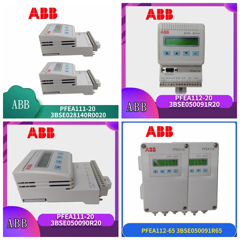
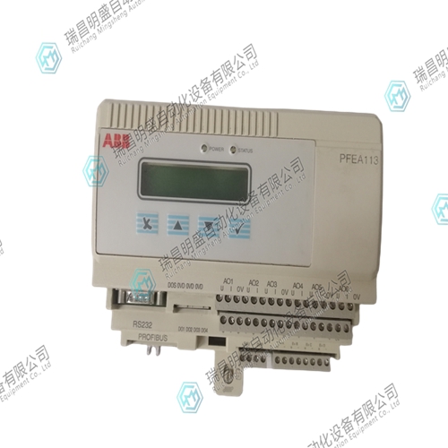
PFEA1130张力传感器
设置缠绕增益
设置缠绕增益为了能够在显示器上显示实际的卷筒纸张力,必须确定卷筒纸张力与称重传感器上测得的力之间的比率。该比率是一个称为包裹增益的缩放因子。包裹增益取决于卷筒纸在测量辊上的包裹角度和称重传感器的方向。因此,包裹增益取决于实际安装。这给出了:T(张力)=缠绕增益×FR(称重传感器测量方向上的卷筒纸张力力)图3-9。缠绕增益菜单有两种方法可以通过悬挂重量或计算得出卷筒纸张力与称重传感器上测得的力之间的比率。•使用悬吊重量(菜单悬吊重量)将一根绳子精确地沿着卷筒纸路径系起来,并施加已知的重量。所施加的已知重量模拟实际的卷筒纸张力,电子设备测量由所施加的重量引起的称重传感器上的合力。当已知卷筒纸张力(T)和相应的测量力(FR)时,张力电子设备计算比率T/FR,并将该值存储为缠绕增益。当卷筒上施加卷筒张力时,张力电子设备通过将测得的称重传感器上的力乘以缠绕增益来计算卷筒张力。悬挂重量程序后,可在EnterWrapGain菜单中找到张力电子设备计算的包裹增益。图3-10.使用悬挂权重设置缠绕增益(安装示例)S 悬挂重量N 从零设置到电压输出称重传感器重量绳索支撑辊所有辊必须是自由转动的惰轮。为了保持低摩擦损失,仅使用最近的辊来定义卷筒纸路径。Tension Electronics PFEA111/112,
用户手册
5节设置缠绕增益3BSE029380R0001 3-17•通过计算(菜单EnterWrapGain)缠绕增益是一个缩放因子,对应于卷筒纸张力(T)与沿称重传感器测量方向作用的卷筒纸张力的力分量(FR)之间的比率。包裹增益范围为0.5-10。如果您试图将包裹增益设置在此范围之外,显示屏上将显示消息“OutOfRange”。包裹增益可以设置为0.01的分辨率。描述包裹增益计算原理的示例:关于安装的称重传感器类型,请参见附录(B、C、D或E)中的包裹增益计算。T T T T F R FR FR=2T FR=T FR<T FR低于T缠绕角缠绕增益=0.50缠绕增益==0.50包裹增益===1.00缠绕增益=(最小缠绕增益值)缠绕增益=缠绕增益=>1(最大允许值缠绕增益=1.00 T FR T 2T FR T T T FR缠绕增益为10)张力电子PFEA111/112,用户手册第3章调试3-18 3BSE029380R0001 6电压输出图3-11。电压输出菜单SetObject FastSetUp WebTension PresentationMenu NominalLoad ServiceMenu ZeroSet SetWrapGain>5 s CurrentOutput Voltage输出杂项菜单从SetWrapGain到VoltageOutput StepResponseTimeHighTension[.]N HighOutput[.]V LowOutput[.]V Low Limit[.]V HighLimit[.]V StepRespenseTime ZZ HighTeension 。 N高输出。 V低输出。 V低压。 N下限。 V上限。 V CurrentOutput Tension Electronics PFEA111/112,用户手册第6节电压输出3BSE029380R0001 3-19可设置以下参数:•阶跃响应时间(滤波)见表3-2。•高压(N,kN,kg,lbs),(出厂默认值=2000 N)•高输出(出厂默认=+10 V)•低压(N,kN,kg,lb),(工厂默认值=0 N)•低输出,(出厂默认值=0 V)•上限,(出厂默认=+11 V)•下限,(出厂缺省值=-5 V)图3-12。如果电压输出信号过快或补偿侧倾不平衡,可使用参数定义滤波。滤波器为线性相位型,最大平坦,20 dB/decade。表3-2.滤波阶跃响应时间0-90%截止频率-3dB 15 ms 35 Hz 75 ms 5 Hz 250 ms 1.5 Hz 750 ms 0.5 Hz卷筒纸张力N,kN,kg,lbs电压输出[V]上限高输出低输出下限低压高压电子设备PFEA111/112.
Set winding gain
Setting the winding gain In order to display the actual web tension on the display, the ratio between the web tension and the force measured on the load cell must be determined. This ratio is a scaling factor called wrap gain. The package gain depends on the package angle of the web on the measuring roll and the direction of the load cell. Therefore, the package gain depends on the actual installation. This gives: T (tension)=winding gain × FR (web tension force in the measuring direction of load cell) Figure 3-9. The winding gain menu has two methods to obtain the ratio between the web tension and the force measured on the load cell by hanging the weight or calculating. • Use the suspended weight (menu suspended weight) to tie a rope precisely along the web path and apply a known weight. The applied known weight simulates the actual web tension, and the electronic equipment measures the resultant force on the load cell caused by the applied weight. When the web tension (T) and the corresponding measured force (FR) are known, the tension electronics calculates the ratio T/FR and stores this value as the winding gain. When the reel tension is applied to the reel, the tension electronics calculates the reel tension by multiplying the measured force on the load cell by the winding gain. After hanging the weight program, the package gain calculated by the tension electronics can be found in the EnterWrapGain menu. Figure 3-10. Use suspension weight to set winding gain (installation example) S suspension weight N from zero setting to voltage output load cell weight Rope support rollers All rollers must be free running idlers. To maintain low friction losses, only the nearest roll is used to define the web path. Tension Electronics PFEA111/112,
user 's manual
Section 5: Set the winding gain 3BSE029380R0001 3-17 • By calculating (menu EnterWrapGain), the winding gain is a scaling factor, which corresponds to the ratio between the web tension (T) and the force component (FR) of the web tension acting along the measuring direction of the load cell. The package gain range is 0.5-10. If you try to set the package gain outside this range, the message "OutOfRange" will appear on the display. The wrap gain can be set to 0.01 resolution. Example describing the principle of parcel gain calculation: For the type of load cell installed, see parcel gain calculation in Appendix (B, C, D or E). T T T T F R FR FR=2T FR=T FR<T FR is lower than T winding angle winding gain=0.50 winding gain==0.50 wrapping gain==1.00 winding gain=(minimum winding gain value) winding gain=winding gain=>1 (maximum allowable winding gain=1.00 T FR T 2T FR T T FR winding gain is 10) tension electronic PFEA111/112. Chapter 3 of the User's Manual Commissioning 3-18 3BSE029380R0001 6 Voltage Output Figure 3-11. Voltage output menuSetObject FastSetUp WebTension PresentationMenu NominalLoad ServiceMenu ZeroSet SetWrapGain>5 s CurrentOutput Voltage Output Miscellaneous menuSetWrapGain to VoltageOutput StepResponseTimeHighTension [.] N HighOutput [.] V LowOutput [.] V Low Limit [.] V HighLimit [.] V StepResponseTime ZZ HighTension. N High output. V low output. V Low voltage. N lower limit. V upper limit. V CurrentOutput Tension Electronics PFEA111/112, Section 6 of the User's Manual Voltage Output 3BSE029380R0001 3-19, the following parameters can be set: • See Table 3-2 for step response time (filtering). • High voltage (N, kN, kg, lbs), (factory default=2000 N) • High output (factory default=+10 V) • Low voltage (N, kN, kg, lb), (factory default=0 N) • Low output, (factory default=0 V) • Upper limit, (factory default=+11 V) • Lower limit, (factory default=- 5 V) Figure 3-12. If the voltage output signal is too fast or compensates for roll imbalance, the filter can be defined using parameters. The filter is linear phase type, maximum flat, 20 dB/decade. Table 3-2. Filter step response time 0-90% cut-off frequency - 3dB 15 ms 35 Hz 75 ms 5 Hz 250 ms 1.5 Hz 750 ms 0.5 Hz web tension N, kN, kg, lbs voltage output [V] upper limit high output low output lower limit low-voltage high-voltage electronic equipment PFEA111/112


