6026BZ10400 DCS集散控制系统
采用无缓冲64通道输入多路复用器
系统集成商在使用该板时必须考虑电源阻抗和电缆长度, 如果这些信号调节产品与一起使用, 在不使用信号调节板或要求极低噪声的应用中,建议使用。功能特性(通常在+25°C和额定电源下,除非另有说明。)操作模式:自动扫描模式:通过重置操作或清除两个CSR模式控制位来选择此默认操作模式。在此模式下连续扫描所有活动通道,并且可以随时读取任何通道值。单通道随机轮询模式:单独访问每个输入通道,并从转换器数据寄存器(CDR)读取数字化通道值。定时脉冲串模式:在编程间隔结束时采集单个数据脉冲串(扫描所有缓冲区位置),或者该过程可以重复。局部触发脉冲串:通过控制和状态寄存器(CSR)启动单个脉冲串。远程触发脉冲串:外部TTL触发源通过P2连接器启动单个数据脉冲串(扫描所有启用的通道)。增益加载模式:如果电路板为跳线配置用于自动增益控制,则通过首先选择增益加载模式,然后将每个通道的增益代码加载到64位增益缓冲器来执行增益加载。所有通道的增益码(0用于x1,1用于x10,2用于x100)在复位操作后自动初始化为零(增益=x1)。
通道自动增益:
每个通道的唯一增益代码从VME总线加载到增益缓冲器中(参见增益加载模式)。对于每个信道采集,从缓冲器中实时检索分配的代码。同步:单个扫描或脉冲串可以由外部TTL触发器通过P2连接器(远程触发脉冲串)或本地通过CSR(本地触发脉冲串。任一事件都会生成P2触发输出,可用于同步多达15个板。板地址:跳线位于短I/O A16空间或标准A24空间中的字边界上。所需的字边界在两个空格中均为1000h。访问:对地址修饰符的响应可跳线选择为:短I/O A16或标准A24地址空间监控或用户权限,或数据或程序访问合规性:本产品符合规范ANSI/IEEE STD 1014-1987 IEC 821和297,具有以下助记符:A24/A16:D16/D8(EO)DTB从中断器I(1至7)ROAK(DYN)中断器矢量:D08(O)(DYN)6U形状因子中断:在除自动扫描外的所有模式下,可以在缓冲区扫描结束时生成中断请求模式响应向量通过中断向量寄存器控制。数据就绪标志:当数据缓冲区已满(endscan)或半满(midscan)时,CSR中的数据就绪标志被设置。间隔定时器:可编程间隔定时器提供高达536秒的突发间隔。复位操作:板复位是响应系统复位或通过在CSR中设置复位位而发生的。对于无编程初始操作,重置操作自动建立以下默认条件:自动扫描模式64通道块大小64通道数据缓冲器通道增益=x1
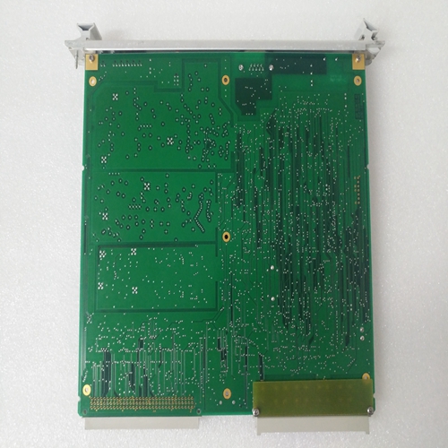
64 channel input multiplexer without buffer
The system integrator must consider the power impedance and cable length when using this board. If these signal conditioning products are used together, they are recommended to be used in applications that do not use signal conditioning boards or require very low noise. Functional characteristics (usually at+25 ° C and rated power supply, unless otherwise stated.) Operation mode: Automatic scanning mode: select this default operation mode by resetting operation or clearing two CSR mode control bits. In this mode, all active channels are scanned continuously, and any channel value can be read at any time. Single channel random polling mode: access each input channel separately and read the digitized channel value from the converter data register (CDR). Timing pulse train mode: collect a single data pulse train at the end of the programming interval (scan all buffer positions), or the process can be repeated. Local trigger pulse train: start a single pulse train through the control and status register (CSR). Remote trigger pulse train: the external TTL trigger source starts a single data pulse train through the P2 connector (scans all enabled channels). Gain loading mode: If the circuit board is configured with jumpers for automatic gain control, perform gain loading by first selecting the gain loading mode, and then loading the gain code of each channel into the 64 bit gain buffer. The gain codes of all channels (0 for x1, 1 for x10, and 2 for x100) are automatically initialized to zero (gain=x1) after the reset operation.
Channel Auto Gain:
The unique gain code for each channel is loaded into the gain buffer from the VME bus (see Gain Loading Mode). For each channel acquisition, the allocated code is retrieved in real time from the buffer. Synchronization: a single scan or pulse train can be triggered by an external TTL trigger via the P2 connector (remote trigger pulse train) or locally via CSR (Local trigger pulse string. Any event will generate P2 trigger output, which can be used to synchronize up to 15 boards. Board address: the jumper is located on the word boundary in the short I/O A16 space or the standard A24 space. The required word boundary is 1000h in both spaces. Access: the response to the address modifier The jumper can be selected as: short I/O A16 or standard A24 address space monitoring or user permissions, or data or program access compliance: the product is compliant ANSI/IEEE STD 1014-1987 IEC 821 and 297, with the following mnemonics: A24/A16: D16/D8 (EO) DTB from interrupter I (1 to 7) ROAK (DYN) Interrupter vector: D08 (O) (DYN) 6U shape factor Interrupt: In all modes except automatic scanning, interrupt request mode response vector can be generated at the end of buffer scanning, and controlled by interrupt vector register. Data Ready Flag: When the data buffer is full (endscan) or half full (midscan), the data ready flag in CSR is set. Interval timer: programmable interval timer provides up to 536 seconds of burst interval. Reset operation: board reset occurs in response to system reset or by setting the reset bit in CSR. For an initial operation without programming, the reset operation automatically establishes the following default conditions: Autoscan mode 64 channel block size 64 channel data buffer channel gain=x1


