


52820083-LF模块备件控制器
数字输入模块
数字输入模块向INFI 90®OPEN系统提供16个独立的数字信号,用于处理和监控。它将过程现场输入与INFI 90 OPEN战略过程管理系统连接起来。触点闭合或开关是提供数字信号的设备的一个示例。控制模块提供控制功能;I/O模块提供输入和输出。本说明介绍了模块的四种变体:2-24 VDC、48 VDC、125 VDC或120 VAC输入。3-24 VDC输入。4-48 VDC输入。5-125 VDC或120 VAC输入。2在功能上等同于现有的IMDSI02模块,其限制是IMDSI01提供1.5毫秒(快)和17毫秒(慢)的可选去抖动滤波器时间,而12模块仅提供17毫秒(慢速)的去抖动滤波器。慢去抖动滤波器用于大多数数字输入应用。在使用适当跳线设置的情况下,任何模块都可以代替IMDSI02。例如,可以用3模块代替IMDSI02模块,该模块的所有跳线都设置为24 VDC,并带有慢速去抖动滤波器。 了INFI 90 OPEN通信电平和这些电平内数字输入模块的位置.
电缆输入数字信号
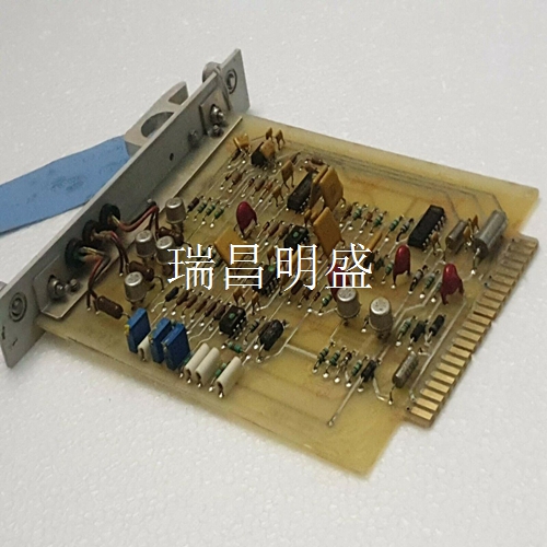
作为52820083-LF数字输入模块的技术信息来源。计划购买、安装、操作、故障排除、维护或更换这些模块的人员应使用本说明。使用数字输入模块的人员应具有使用交流/直流电源的经验,并了解应采取的预防措施。还需要了解INFI 90 OPEN系统和电子原理。模块描述数字输入模块由占据模块安装单元(MMU)中一个插槽的单个印刷电路板组成。它监控两组独立的八个数字输入。12个输入彼此隔离;其余两对共用公共正输入线。模块面板上的两个固定螺钉将其固定至MMU。16个前面板LED状态指示灯(A组和B组)显示输入状态,并在系统测试和诊断中提供帮助。数字输入模块有三个用于外部信号和电源(P1、P2和P3)的卡边缘连接器。P1连接到公共(接地)和+5 VDC电源。P2将模块连接到I/O扩展器总线以与控制模块通信。P3使用连接到终端单元(TU)或终端模块(TM)的电缆输入数字信号。现场接线的接线板(物理连接点)位于TU/TM上。.
Digital input module
Digital input module to INFI 90 ® OPEN system provides 16 independent digital signals for processing and monitoring. It connects process field input with INFI 90 OPEN strategic process management system. A contact closure or switch is an example of a device that provides a digital signal. The control module provides control functions; I/O modules provide inputs and outputs. This description describes the four variants of the module: 2-24 VDC, 48 VDC, 125 VDC, or 120 VAC inputs. 3-24 VDC input. 4-48 VDC input. 5-125 VDC or 120 VAC input. 2. It is functionally equivalent to the existing IMDSI02 module. The limitation is that IMDSI01 provides 1.5 ms (fast) and 17 ms (slow) optional dither filter time, while the 12 module only provides 17 ms (slow) dither filter time. Slow de jitter filters are used for most digital input applications. Any module can replace IMDSI02 with appropriate jumper settings. For example, the IMDSI02 module can be replaced by three modules, all jumpers of which are set to 24 VDC and have a slow jitter filter. INFI 90 OPEN communication level and the position of digital input module in these levels.
Cable input digital signal
As a source of technical information for the 52820083-LF Digital Input Module. This instruction should be used by those planning to purchase, install, operate, troubleshoot, maintain, or replace these modules. Personnel using digital input modules should have experience in using AC/DC power supplies and understand the precautions to be taken. You also need to know INFI 90 OPEN system and electronic principle. Module Description The digital input module consists of a single printed circuit board occupying a slot in the module mounting unit (MMU). It monitors two independent sets of eight digital inputs. The 12 inputs are isolated from each other; The other two pairs share a common positive input line. Two fixing screws on the module panel secure it to the MMU. The 16 front panel LED status indicators (Group A and Group B) display the input status and provide assistance in system testing and diagnostics. The Digital Input Module has three card edge connectors for external signals and power supplies (P1, P2, and P3). P1 is connected to a common (ground) and+5 VDC power supply. P2 connects the module to the I/O expander bus to communicate with the control module. P3 uses a cable connected to the terminal unit (TU) or terminal module (TM) to input digital signals. The terminal block (physical connection point) for field wiring is located on the TU/TM.
")
")
")

