DEIF DELOMATIC-3控制通信板
参考NTCL01终端装置或NICL01终端模块手册,了解完整的终端设备信息。附录A和B提供了有关这些终端设备的快速参考信息。用一个NIS模块安装一个INICT01 INFI-NET到计算机传输模块(ICT),以形成INICT01-INFI-NET到计算机接口。INICT01模块由两块电路板(一块内存电路板和一块CPU电路板)组成。内存板没有用户可配置的操作选项。CPU电路板有三个双列直插式开关,用于设置模块操作特性。这些双列直插式开关可选择模块操作选项、串行端口通信特性和波特率。图3-3显示了CPU电路板上的双列直插式开关位置。注意:跳线J1至J3为出厂设置。请勿更改跳线设置。双列直插式开关U72是一个八极双列直拨式开关,用于确定ICT模块的操作选项。表3-7列出了双列直插式开关U72选项设置。在提供的空间中记录双列直插式开关U72的设置。1.选择此选项将自动覆盖双列直连式开关位置2和3,并将端口1的数据特性设置为8个数据位、1个停止位和无奇偶校验位。当未选择此选项时,双列直插开关极2和3保持完全功能。2.启用此选项时,ICT模块期望来自主机的所有命令将通过实用程序菜单配置的端口地址作为每个命令的第一个字符发送。3.当启用此选项时,ICT模块期望来自主机的所有命令包括校验和字节作为回车前的最后一个字符。ICT模块在每个答复中都包含一个校验和
双列直插式开关U73-串行端口通信速率
双列直插式开关U73是一个八极双列直连式开关,用于设置串行端口(RS-233-C)通信速率。通信速率直接影响数据吞吐量。通信速率见表3-8。在提供的空间中记录双列直插式开关U73的设置。双列直插式开关U75启用计算机接口诊断功能,这些功能仅对合格的贝利控制公司服务人员有意义。必须关闭双列直插式开关U75上的所有极才能正常工作。表3-9显示了双列直插式开关设置。确认双列直插式开关U75上的所有极均设置为零(闭合或接通)。如果ICT模块配置正确,即可安装在模块安装单元中。安装ICT模块:1.验证模块安装单元中的ICT模块插槽分配是否与其相关的NIS模块相邻。2.验证在NIS模块使用的模块安装单元插槽和ICT模块使用的插槽之间的I/O扩展器总线插槽中安装了24针双探针。注:安装带有ICT模块的NIS模块时,NIS模块和ICT模块CPU电路板之间必须保持连续性。注意以下事项:a.如果NIS模块安装在ICT模块的左侧,则在NIS插槽和ICT插槽之间的I/O扩展器总线插槽中安装一个双探针。b、 如果NIS模块安装在ICT模块的右侧,则需要进行两次下探。在NIS插槽和ICT插槽之间安装一个双头探针。在ICT模块的内存电路板和CPU电路板的插槽之间安装第二个双探针。
Refer to the NTCL01 termination unit
or NICL01 termination module manual for complete termination device information. Appendix A and B provide quick reference information about these termination devices.Install one INICT01 INFI-NET to Computer Transfer Module (ICT) with one NIS module to make an INICI01 INFI-NET to Computer Interface.The INICT01 module consists of two circuit boards (a memory circuit board and a CPU circuit board). The memory board has no user-configurable operating options. The CPU circuit board has three dipswitches that set the module operating characteristics. These dipswitches select module operation options, serial port communication characteristics and baud rate. Figure 3-3 shows the dipswitch locations on the CPU circuit board. NOTE: Jumpers J1 through J3 are factory set. Do not change the jumper settings.Dipswitch U72 is an eight pole dipswitch that determines the operating options of the ICT module. Table 3-7 lists the dipswitch U72 option settings. Record the dipswitch U72 settings in the space provided.1. Selecting this option automatically overrides dipswitch positions 2 and 3 and sets port 1 data characteristics to 8 data bits, 1 stop bit, and no parity bit. Dipswitch poles 2 and 3 retain full functionality when this option is not selected. 2. When this option is enabled, the ICT module expects all commands from the host computer to send the port address configured through the utilities menu as the first character of each command. 3. When this option is enabled, the ICT module expects all commands from the host computer to include a checksum byte as the last character before the carriage return. The ICT module includes a checksum in each reply
DIPSWITCH U73 - SERIAL PORT COMMUNICATION RATE
Dipswitch U73 is an eight pole dipswitch that sets the serial port (RS-233-C) communication rate. The communication rate directly affects data throughput. Refer to Table 3-8 for communication rates. Record the dipswitch U73 settings in the space provided.Dipswitch U75 enables computer interface diagnostic functions that are meaningful to qualified Bailey Controls Company service personnel only. All poles on dipswitch U75 must be closed for normal operation. Table 3-9 shows the dipswitch settings. Verify that all poles on dipswitch U75 are set to zero (closed or on).If the ICT module is properly configured, it is ready to be installed in the module mounting unit. To install the ICT module: 1. Verify the ICT module slot assignment in the module mounting unit is adjacent to its associated NIS module.2. Verify that a 24-pin dipshunt is installed in the I/O expander bus sockets between the module mounting unit slot to be used by the NIS module and the slot to be used by the ICT module. NOTE: When installing the NIS module with an ICT module, there must be continuity between the NIS module and the CPU circuit board of the ICT module. Observe the following: a. Install one dipshunt in the I/O expander bus socket between the NIS slot and ICT slot if the NIS module is mounted to the left of the ICT module. b. If the NIS module is mounted to the right of the ICT module, two dipshunts are required. Install one dipshunt between the NIS slot and ICT slot. Install the second dipshunt between the slots of the memory circuit board and the CPU circuit board of the ICT module.
产品优势
1:国外专业的供货渠道,具有价格优势
2:产品质量保证,让您售后无忧
3:全国快递包邮
4:一对一服务
公司主营范围简介
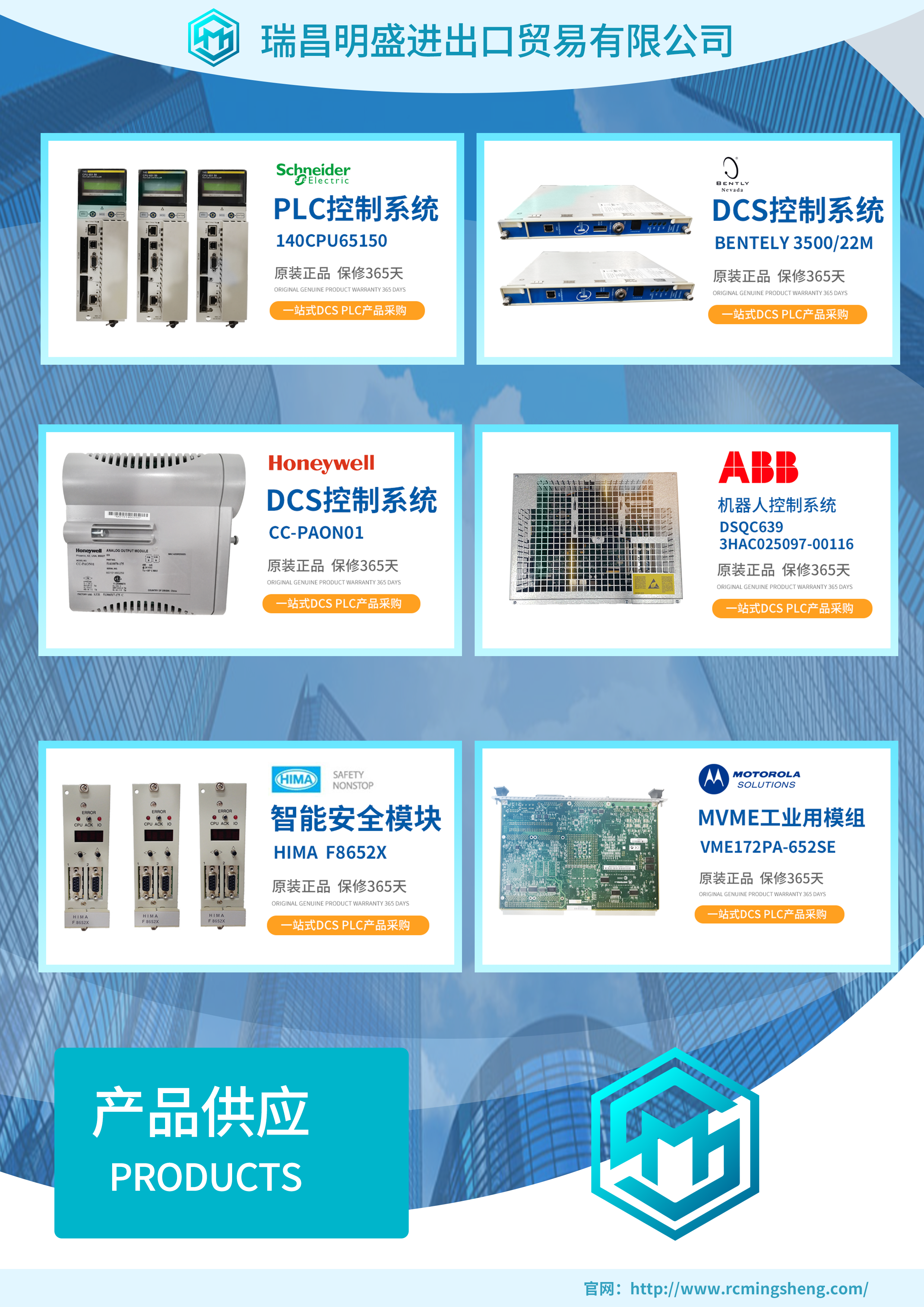
PLC可编程控制器模块,DCS卡件,ESD系统卡件,振动监测系统卡件,汽轮机控制系统模块,燃气发电机备件等,优势品牌:Allen Bradley、BentlyNevada、ABB、Emerson Ovation、Honeywell DCS、Rockwell ICS Triplex、FOXBORO、Schneider PLC、GE Fanuc、Motorola、HIMA、TRICONEX、Prosoft等各种进口工业零部件、欧美进口模块。
产品广泛应用于冶金、石油天然气、玻璃制造业、铝业、石油化工、煤矿、造纸印刷、纺织印染、机械、电子制造、汽车制造、塑胶机械、电力、水利、水处理/环保、锅炉供暖、能源、输配电等等


