


产品内容介绍
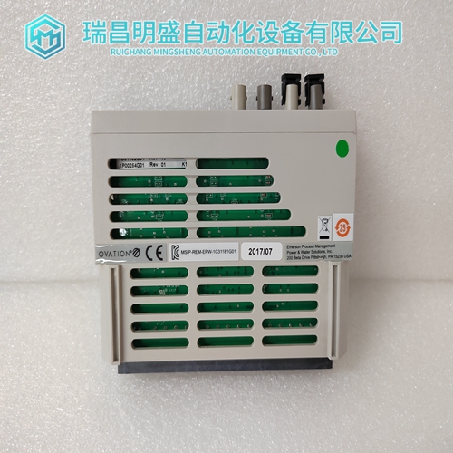
1C31181G01模拟量输出模块
输入选择首先,找到模块左侧的四个检修孔。这些孔允许访问三个四位和一个五位DIP开关。
接下来,设置底部五位DIP开关的开关位置5(SW5模块左侧的检修孔,用于选择输入范围。此开关必须对应八位模块配置DIP的开关位置8(SW8转换SW5和SW8设置必须相同。有两种方法可以配置模块以接受当前输入。有8个差动电流/电压输入模块称为B875-111。有16个单端电流/电压输入模块称为B877-111。
B875-111字段连接为八个差动电流输入配置B875-111时,请注意将接收这些输入的通道。通过放置正极电压输入和电流之间的磁场连接器上的跳线相应通道的输入端子。例如,如果通道2要接收电流输入,必须在端子#7(CH2)和端子#6之间跳线(电流输入CH2),如下图所示。下图显示了B875的简化示意图–111模块。
B875–111模拟输入模块,电流输入示例图开路电压输入可能正或负漂移。如果需要开路检测,应使用电流输入。使用电压时输入,如果电阻值较大(2 MΩ 或更大)是放置在正极(+)和负极(-)输入之间的现场连接器上。这个如果磁场连接断开。
B877-111字段连接电流输入通过设置可通过侧面访问的DIP开关进行选择用于接收输入的每个通道的盖子。
DIP开关将250Ω 精确正极输入和模拟回路之间的电阻。
位于左侧的开关组4上的第五个开关(SW5)选择电压范围此开关的位置必须与模块配置的位置相同开关SW8,位于模块后部。
请参阅左侧的标签模块侧面,以及下面显示单端输入(B877)的当前设置的图示。
单端输入的电流设置,图(B877)1配置模块时,将现场侧接线连接至现场连接器上的适当引脚用于16个单端输入。
注:开路电压输入可能正或负漂移。如果断路需要检测,应使用电流输入。
当使用电压输入时如果电阻值较大(2 MΩ 或更大)放置在正极(+)和负极(-)输入之间的磁场连接器。电阻器夹住如果磁场连接断开,则通道至小偏移电压(<100 mV)。2重新安装临时卸下的任何模块。
3当使用键销(随外壳装运提供)时,将其安装在上方和下方为该模块的安装选择了外壳插槽。
4将模块牢固但小心地插入外壳,将边缘连接器固定在底板上。
5使用顶部和底部的外加开槽安装螺钉将模块固定到外壳上模块前面板
Input Selection First
locate the four access holes on the left side of the module. These holes allow access to three four-position and one five-position DIP switch. Next, set switch position 5 (SW5) of the five-position DIP switch found in the bottom access hole on the left side of the module, to select the input range. This switch must correspond to switch position 8 (SW8) of the eight-position module configuration DIP switch. SW5 and SW8 settings must be identical.There are two ways to configure the module to accept current inputs. With eight differential current/voltage inputs the module is called the B875-111. With sixteen single-ended current/voltage inputs the module is called the B877-111. B875-111 field connections When configuring the B875-111 for eight differential current inputs, note the channels that will receive these inputs. Current inputs are selected by placing a jumper on the field connector between the positive voltage input and the current input terminal for the appropriate channel. For example, if channel 2 is to receive a current input, a jumper must be made between terminal #7 (CH2) and terminal #6 (Current Input CH2), as shown on the following illustration. The following illustration represents the simplified schematic diagram for the B875– 111 module. B875–111 Analog Input Module, Current Input Example Drawing
Open-circuit voltage inputs may drift either positive or negatively. If opencircuit detection is required, a current input should be used. When using voltage inputs, an open circuit can be detected if a large-value resistor (2 MΩ or greater) is placed at the field connector across the positive (+) and negative (-) inputs. The resistor clamps the channel to a small offset voltage (<100 mV) if the field connections are broken.
B877-111 Field Connections
Current inputs are selected by setting the DIP switches accessible through the side cover for each channel to receive an input. The DIP switch places a 250 Ω precision resistor between the positive input and analog returns. The fifth switch (SW5) on switch bank 4, located on the left side selects the voltage range. The position of this switch must be the same as for module configuration switch SW8, located at the rear of the module.Refer to the label located on the left side of the module, and to the illustration showing the current settings for singleended inputs (B877) below. Current Settings for Single-Ended Inputs, Diagram (B877)1 Connect field-side wiring to proper pins on field connector when module is configured for sixteen single-ended inputs. Note: Open-circuit voltage inputs may drift either positive or negatively. If open-circuit detection is required, a current input should be used. When using voltage inputs, an open circuit can be detected if a large-value resistor (2 MΩ or greater) is placed at the field connector across the positive (+) and negative (-) inputs. The resistor clamps the channel to a small offset voltage (<100 mV) if the field connections are broken. 2 Reinstall any module temporarily removed. 3 When using key pins (provided with housing shipment), install them above and below housing slot selected for this module’s installation. 4 Insert module into housing firmly but carefully, seating edge connector in backplane. 5 Secure module to housing using captive slotted mounting screws at top and bottom of module front panel
")
")
公司主营产品图展示
")
产品优势
1:国外专业的供货渠道,具有价格优势
2:产品质量保证,让您售后无忧
3:全国快递包邮
4:一对一服务
公司主营范围简介
PLC可编程控制器模块,DCS卡件,ESD系统卡件,振动监测系统卡件,汽轮机控制系统模块,燃气发电机备件等,优势品牌:Allen Bradley、BentlyNevada、ABB、Emerson Ovation、Honeywell DCS、Rockwell ICS Triplex、FOXBORO、Schneider PLC、GE Fanuc、Motorola、HIMA、TRICONEX、Prosoft等各种进口工业零部件、欧美进口模块。
产品广泛应用于冶金、石油天然气、玻璃制造业、铝业、石油化工、煤矿、造纸印刷、纺织印染、机械、电子制造、汽车制造、塑胶机械、电力、水利、水处理/环保、锅炉供暖、能源、输配电等等

