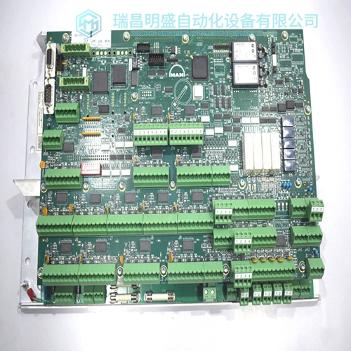
产品详情内容介绍
DYNOMAX 10-2A-B-1165驱动控制减速机
信道抑制按下工程卡INHIBIT(禁止)按钮可切换选定的控制卡通道抑制模式介于打开和关闭之间。
当抑制模式设置为打开时,从工程部本地卡或远程抑制输入,所选控制卡:
a、 通道抑制继电器(如已配置)启动。
b、 通道LED显示持续琥珀色以指示INHIBIT(抑制)。
c、 其余通道继电器锁定在非活动状态。
要选择禁止功能,请执行以下操作:
(1) 将工程钥匙插入工程卡前面板插座,并检查解锁指示灯()是否亮起。
(2) 按住所需的控制卡重置/选择按钮约1.5秒,检查所选的控制卡通过显示选择来指示它已被选中
(3) 使用工程卡()和()按钮选择所需通道。
(4) 按下INHIBIT(抑制)按钮以打开通道抑制模式/关闭。报警配置和继电器测试操作通过不同的
阶段如下:
a、 设置A1、A2、A3、STEL、LTEL的阈值。这些阶段用于设置A1、A2、A3、STEL和LTEL警报阈值点,不影响报警LED和继电器。
b、 A1、A2、A3、故障、STEL、LTEL的测试灯和可选继电器。
这些阶段提供灯测试和继电器测试功能。
注:未配置STEL/LTEL阈值时,一行破折号将显示而不是标高和STEL和LTEL设施将永久设置为关闭。
要选择报警配置操作,请执行以下操作:
(1) 将工程钥匙插入工程卡前面板插座,并检查解锁指示灯()是否亮起。
(2) 按住所需的控制卡重置/选择按钮约1.5秒,检查所选的控制卡通过显示选择来指示它已被选中偶像
(3) 使用工程卡()和()按钮选择所需通道。
(4) 第一次按下工程卡报警按钮。
(5) 检查所选控制卡信息显示屏是否显示A1上升报警阈值或A1代表下降报警阈值交替使用选定的频道编号。
(6) 检查所选控制卡数字显示器是否指示A1报警阈值。
模拟显示屏继续实时显示传感器测量
1.只有在控制卡已为此警报配置。
2.测试功能自动禁用控制卡允许对通道进行显示测试和指示灯测试的通道
LED报警指示,防止意外报警生成。为了测试继电器和故障指示,必须使用INHIBIT(禁止)按钮来设置控制卡进入不受限制的状态。
3.在测试中,可以取消选择所选控制卡按下所选控制卡前面板RESET/选择按钮。模拟气体液位和继电器状态将保持设置,允许多个控制卡同时测试。重新选择控制卡时卡将返回测试模式。ATTN LED指示灯哪些卡在报警测试模式下具有通道。
4.如果禁用被解除,外部继电器将运行。
ALARM CONFIGURATION AND RELAY TEST
The alarm configuration and relay test operation cycles through different stages as follows: a. Set thresholds for A1, A2, A3, STEL, LTEL. These stages are used to set the A1, A2, A3, STEL and LTEL alarm threshold points and do not affect the alarm LEDs and relays. b. Test lamps and optional relays for A1, A2, A3, Fault, STEL, LTEL. These stages provide a lamp test and relay test function. Note: When not configured for STEL/LTEL threshold, a row of dashes will be displayed instead of a level and the STEL and LTEL faclilities will be set permanently to off. To select the alarm configuration operation, proceed as follows: (1) Plug the Engineering Key into the Engineering Card front panel socket and check that the Unlocked LED ( ) is illuminated. (2) Push and hold the required control card RESET/SELECT pushbutton for approximately 1.5 seconds and check that the selected control card indicates it has been selected by displaying the select icon. (3) Use the Engineering Card ( ) and ( ) push-buttons to select the required channel. (4) Push the Engineering Card ALARMS push-button for the first time. (5) Check that the selected control card message display shows A1 for a rising alarm threshold or A1 for a falling alarm threshold alternating with the selected channel number. (6) Check that the selected control card digital display indicates the A1 alarm threshold point. Note: The analogue display continues to show the sensor live measurement.
CHANNEL INHIBIT
Pushing the Engineering Card INHIBIT push-button toggles the selected control card channel inhibit mode between on and off. When the inhibit mode is set to on, either locally from the Engineering Card or remotely by the Remote Inhibit input, the selected control card: a. channel inhibit relay, if configured, is actuated. b. channel LED shows continuous amber to indicate INHIBIT. c. remaining channel relays are locked in their non-active state. To select the inhibit function, proceed as follows: (1) Plug the Engineering Key into the Engineering Card front panel socket and check that the Unlocked LED ( ) is illuminated. (2) Push and hold the required control card RESET/SELECT pushbutton for approximately 1.5 seconds and check that the selected control card indicates it has been selected by displaying the select icon. (3) Use the Engineering Card ( ) and ( ) push-buttons to select the required channel. (4) Push the INHIBIT push-button to toggle the channels inhibit mode on/ off.
: 1. The LTEL Alarm can only be switched on if the Control Card has been configured for this alarm. 2. The TEST function automatically inhibits the control card channel to allow a display test and a lamp test of the channel LED alarm indications and prevent accidental alarms being generated. In order to test the relays and FAULT indications, the INHIBIT push-button must be used to set the control card channel into the uninhibited state. 3. A selected control card may be deselected while in the TEST mode by pushing the selected control card front panel RESET/ SELECT push-button. The simulated gas level and relay states will remain set allowing several control cards to be tested simultaneously. When the control card is reselected the card will return to the TEST mode. The ATTN LED indicates which cards have channels in the alarm test mode. 4. If the inhibit is removed, the external relays will operate.
公司主营产品图展示

产品优势
1:国外专业的供货渠道,具有价格优势
2:产品质量保证,让您售后无忧
3:全国快递包邮
4:一对一服务
公司主营产品文字介绍
PLC可编程控制器模块,DCS卡件,ESD系统卡件,振动监测系统卡件,汽轮机控制系统模块,燃气发电机备件等,优势品牌:Allen Bradley、BentlyNevada、ABB、Emerson Ovation、Honeywell DCS、Rockwell ICS Triplex、FOXBORO、Schneider PLC、GE Fanuc、Motorola、HIMA、TRICONEX、Prosoft等各种进口工业零部件、欧美进口模块。
产品广泛应用于冶金、石油天然气、玻璃制造业、铝业、石油化工、煤矿、造纸印刷、纺织印染、机械、电子制造、汽车制造、塑胶机械、电力、水利、水处理/环保、锅炉供暖、能源、输配电等等


