


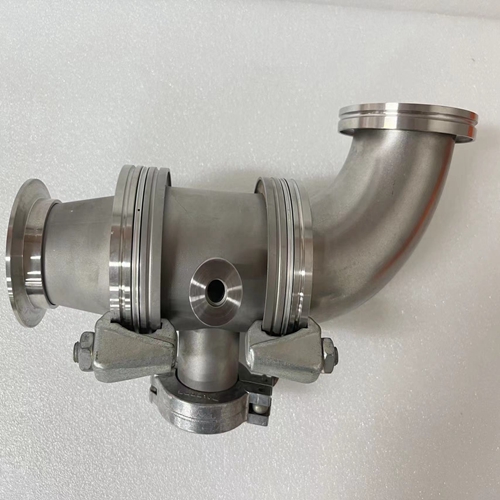
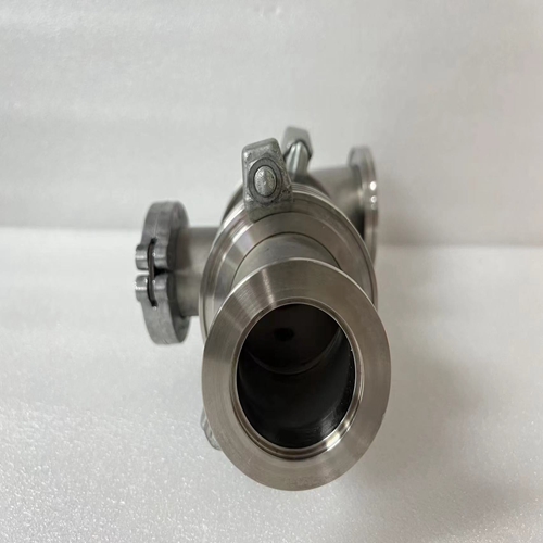
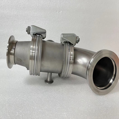
公司主营产品图展示
")
产品优势
1:国外专业的供货渠道,具有价格优势
2:产品质量保证,让您售后无忧
3:全国快递包邮
4:一对一服务
产品详情介绍
BALZERS IKR020底座
阻止复制时间,复制时间输入信号或输出
来自/到传输的信号记忆力
它包括:–净拷贝时间0.2毫秒
–2个接口中断每个0.1毫秒–如果由远程模块扩展,则等待访问时间
授权:二进制模块。仅:1.1毫秒,也是模拟模块:2.7毫秒
(开启2倍询问时间CS31系统总线)该等式假设处理器总是在最不利的时刻进入。
循环时间tC存储在KD 00,00中,可以是以5毫秒时间步长选择。如果所选循环时间为太短,处理器将无法完成任务分配给它。届时它将默认。如果这种时间不足在几个周期内变得过大,处理器将中止程序执行和输出错误(FK2)。使用一些功能块,例如PID控制器,无错误执行取决于精确的定时序列确保有更大的时间储备。循环时间的正确设置可以通过以下方式进行检查以下程序:–将用户程序加载到中央单元。
–如果操作模式已从单机到总线主机:电源打开或菜单项编程软件中的“启用PLC模式”。
–使用菜单查询容量利用率“显示PLC状态”项。
–更改周期时间tC,直到容量利用率低于80%。
总线主中央单元+1二进制输入模块+1二进制输出模块
+2个模拟输入模块不考虑地址范围,以下模块可以连接到CS31系统总线:
–最多1个总线主机
–最多31个远程模块/从机中央单元07 KR 91/07 KT 92/93的地址范围造成了进一步的限制:
–最多12个模拟输入模块
–最多12个模拟输出模块
–最多31个二进制输入模块
–最多31个二进制输出模块
根据安装结构和遥控器类型,可能会有进一步的限制模块。有关建议的地址,请参阅第A2.2章。
Block copy time, time for copying
the input signals or the out-put
signals from/to the transfer
memory.
It includes:
– Net copy time 0.2 ms
– 2 interface interrupts of
0.1 ms each
– If expanded by remote modules, waiting time for access
authorization:
binary mod. only: 1.1 ms,
also analog mod.: 2.7 ms
(2 x interrogation time on
the CS31 system bus)This equation assumes that the processor always gets
access in the most unfavourable moment.
The cycle time tC is stored in KD 00,00 and can be
selected in 5 ms time steps. If the selected cycle time is
too short, the processor will not be able to fulfill the tasks
assigned to it. It will come in default then.If this lack of time is getting too large over several cycles,
the processor will abort the program execution and output
an error (FK2).
Using some function blocks, such as the PID controller,
the error-free execution depends on an exact timing
sequence. Make sure that there is a larger time reserve.
The correct setting of the cycle time can be checked by
the following procedure:
– Loading the user program into the central unit.
– If the operating mode has been switched over from
stand-alone to bus master: Power ON or menu item
”Enable PLC mode” in the programming software.
– Interrogation of the capacity utilization using the menu
item of ”Display PLC status”.
– Changing the cycle time tC until the capacity utilization
is below 80 %.
Example: Bus master central unit + 1 binary input
module + 1 binary output module
+ 2 analog input modules Without regard to the address ranges, the following modules can be connected to a CS31 system bus:
– max. 1 bus master
– max. 31 remote modules / slaves
Further restrictions result from the address range of the central units 07 KR 91 / 07 KT 92/93:
– max. 12 analog input modules
– max. 12 analog output modules
– max. 31 binary input modules
– max. 31 binary output modules
There may be further restrictions according to the structure of the installation and the type of remote
modules. For the recommended addresses, see chapter A2.2.

