


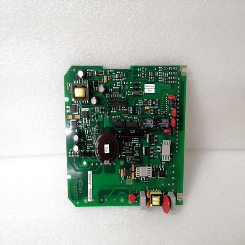
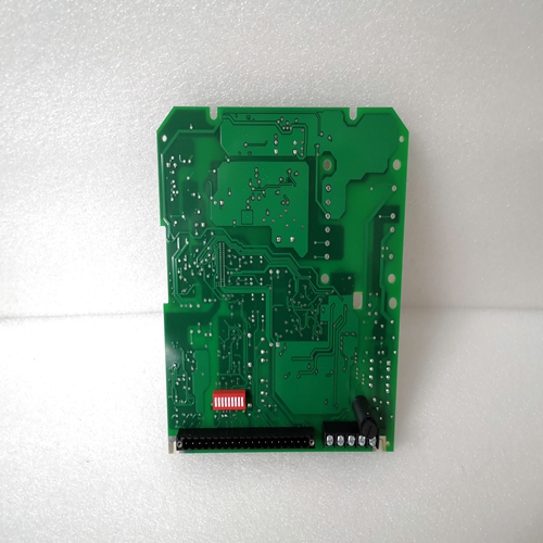
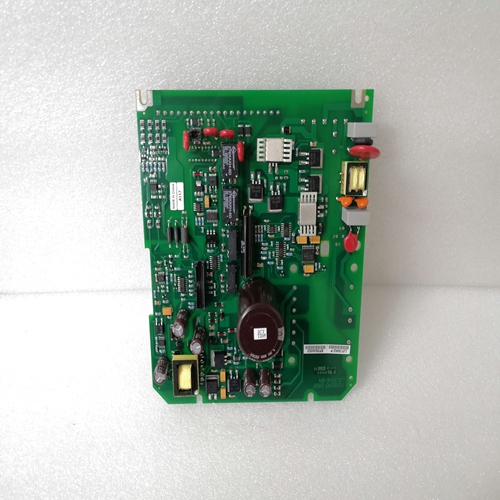
公司主营产品图展示
")
产品优势
1:国外专业的供货渠道,具有价格优势
2:产品质量保证,让您售后无忧
3:全国快递包邮
4:一对一服务
产品详情介绍
L0130AD模拟量卡件
有五种操作模式:–32位计数器增量编码器输入–32位计数器,在通道A和通道B递减
–32位计数器,添加通道A和B
–通道A、B和C三个独立的16位计数器
–三个16位频率计,用于通道A、B和C通过设置DIP选择操作模式开关位于装置后部。
计数器可以设置为检测上升、下降或上升和下降边缘。
4个二进制输入用于计数器数据设置,7个二进制静态输入提供了输出。
输出的状态由比较决定计数器和设定值以及计数方向
该装置必须安装在插入式底座ECZ上。e:当使用230 VAC或120 VAC版本时可使用内部24 VDC电源,前提是不大于50 mA时加载;如果是,外部必须使用24 VDC电源。
仅使用外部电源的0 VDC提供输出不必连接到公共-如果输出必须重置为0切断电源。
如果负载是感应的,则公共-和0V端子必须连接在一起,以避免输出电路内的过电压二极管是内置的,但这会增加响应时间● 初始化配置并接线装置后:–装置在通电后自行初始化。
–初始化后,错误指示灯熄灭。–计数器、阈值重置为0和目标
窗口设置为2。位B0表示数据传输状态,并被检查为从中央单元发送参数和命令到计数器单元。位B1至B4表示二进制输入的状态。位B8至B14表示晶体管输出的状态。如果输入有效关闭,则所有二进制输出重置为0,但内部状态B8-B14始终可用。
配置和诊断可通过访问配置和诊断下面的单词
B7:当机组温度为太高了。所有输出均重置为“O”。
B15:当计数器值超过最大值或当计数器频率太高。
B8:指示计数器的模式操作(插入式底座上的DIP开关n°2)。
–B8=0模式32位(DIP开关n°2打开“on”)
–B8=1模式2 x 16符号位(DIP开关n°2打开“OFF”)
在模式下为2 x 16位。高位字代表低位字的正溢出或负溢出数。
高位字在上以正溢出递增低级单词从+32767到-32768的转换。
以类似的方式,高位字在从低位单词的-32768到+32767的转换。
Five modes of operation are possible :
– 32 bit counter incremental encoder input
– 32 bit counter, incrementing on channel A and
decrementing on channel B
– 32 bit counter, addition of channels A and B
– Three independant 16 bit counters for channel A, B and C
– Three 16 bit frequency meters for channels A,B and C
The mode of operation is selected by setting the DIP
switches on the rear of the unit.
The counters can be set to detect rising, falling or rising
and falling edges.
4 binary inputs for counter data setting and 7 binary static
outputs are provided.
The status of the outputs is determined by the comparison
of the counter(s) and setpoint values and the count
direction.
The unit has to be mounted on a plug-in base ECZ.e : When using the 230 VAC or 120 VAC versions, the
internal 24 VDC supply can be used providing the
load if it is not greater than 50 mA ; if it is, an external
24 VDC power supply must be used.
The 0 VDC of an external power supply used only
to provide the outputs has not to be connected to
the common –, if the outputs have to be reset to 0
with a power off of this supply.
If the load is inductive,the common – and the 0V
terminals must be connected together to avoid
overvoltage within the output circuitry an free weeling
diode is built-in, this however increases the response
time.● Initialization
After configured and wired the unit :
– the unit initializes itself after power On.
– the error led goes out after initialization.
– the counters, the thresholds are reset to 0 and the target
window to 2.Bit B0 indicates the data transfer status and is checked to
sending parameters and commands from the central unit
to the counter unit.
Bits B1 to B4 indicate the status of the binary inputs.
Bits B8 to B14 indicate the status of the transistor outputs.
If the input valid is off, all binary outputs are reset to 0 but
the internal status B8 - B14 is always available.
Configuration and diagnosis
The configuration and diagnosis are accessed with the
following words.B7 : "OVERLOAD" is set when the temperature of the unit
is too high. All of then outputs are reset to "O".
B15 : "OVERFLOW" indicate a counter error , when the
counter value exceeds the maximun or when the counter
frequency is too high.
B8 : indicate the mode operation for the counter (DIPswitch n°2 on the plug in base).
– B8 = 0 mode 32 bits (DIP switch n° 2 on "ON")
– B8 = 1 mode 2 x 16 signed bits(DIP switch n° 2 on "OFF")
In the mode 2 x 16 bit. The high word represents the
number of positive or negative overflows of the low word.
The high word is incremented with a positive overflow on
the transition from + 32767 à – 32768 of the low word.
In a similar manner the high word is decremented on the
transition from – 32768 à + 32767of the low word.

