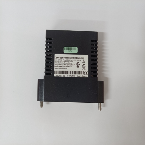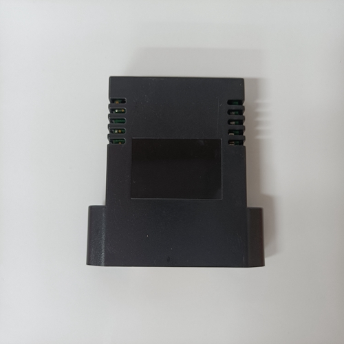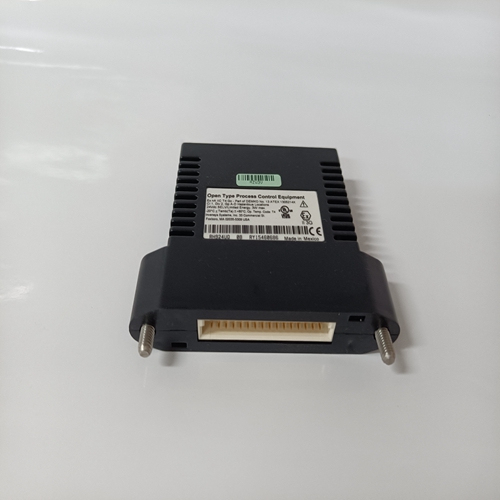
RH924UQ模拟量编程模块
基座电压的振幅由集电极决定第二级差动放大器电流 电流变晶体管Q3齐纳二极管Z2用作电压钳位,电阻器R31和R32为分压器,用于确定可编程单结晶体管Q5。PUT Q5的输出施加到栅极通过电阻器R43和R44以及DIDOE的功率控制器SCRD15和D16以及放大级,二极管D10、电阻器R46和R81以及电容器C24。
功率级(功率控制器):功率级为发电机供电激励器 eld电流。功率级由SCR/二极管电桥组成直肠 呃。功率级输入为单相120 Vac或单相相位240 Vac,取决于调节器设计。功率输出级由其SCR接收的导通选通信号调节来自相位控制电路。该电路包括一个续流二极管对于 感应励磁机的eld放电 eld负载和its中的保险丝(Fl)输入电源线。领域 灰化电路 埃尔德 灰化电路包括SCR1, 埃尔德效应晶体管(FET)Q6、晶体管Q7至Q10、电阻器R34通过R42、R82和R85
二极管D7、D11和D29以及电容器
晶体管Q8和Q9、二极管D7以及电阻器R36、R37和R36,R38、R40和R41包括施密特触发电路。施密特
当电压增加时,触发器开启,且幅度传感标称24 Vdc输出的大约70%
直肠 ers,并在电压降低时关闭大约为传感标称输出的30%直肠 呃。
当施密特触发器断开时,FET Q6接通。此动作接通在晶体管Q10和Q7上 重从SCR1位于电路板上。从SCR1 可控硅直肠 调节器功率控制器电路中的ers SCR1和SCR2
当接通时,向励磁机提供电流 埃尔德。当施密特触发器接通,FET Q6关断。此动作关断晶体管Q10
Q6和Q7,其去除到从SCR1的选通信号的选通信号 来自功率控制器SCR的灰化电路。
电阻器R70和电容器C19在 环功率级SCR。电容器C8和电阻器R45有助于限制传导EMI。二极管D8、D9和功率级电源中的二极管权力 灰化和相位控制电路。
The amplitude of the pedestal voltage is determined by the collector current of second stage differential ampli er transistor Q3. Zener diode Z2 serves as a voltage clamp and resistors R31 and R32 are a voltage divider, which determines the threshold of the programmable unijunction transistor Q5. The output of PUT Q5 is applied to the gate of the power controller SCRs through resistors R43 & R44 and didoes D15 & D16 and an amplifying stage that is comprised of transistor Q11, diode D10, resistors R46 & R81, and capacitor C24. Power stage (power controller): The power stage supplies the generator exciter eld current. The power stage consists of an SCR/diode bridge recti er. The power stage input is either single phase 120 Vac or single phase 240 Vac depending on regulator design. The output of the power stage is regulated by the turn on gating signal that its SCRs receive from the phase control circuit. The circuit includes a free wheeling diode for eld discharge of the inductive exciter eld load and a fuse (Fl) in its input power line. Field ashing circuit: The eld ashing circuit includes SCR1, eld effect transistor (FET) Q6, transistors Q7 through Q10, resistors R34 through R42, R82, and R85, Diodes D7, D11, & D29, and capacitors C25 & C27. Transistors Q8 and Q9, diode D7, and resistors R36, R37, R38, R40, & R41 comprise a Schmidt trigger circuit. The Schmidt trigger turns on when an increasing voltage is present with magnitude approximately 70% of the nominal 24 Vdc output of the sensing recti ers, and turns off when a decreasing voltage is present with magnitude of approximately 30% of the nominal output of the sensing recti er. When the Schmidt trigger is off, FET Q6 is on. This action turns on transistors Q10 and Q7, which supply current to re slave SCR1 located on the circuit board. Slave SCR1 res the silicon controlled recti ers SCR1 and SCR2 in the regulator power controller circuit which, when on, supply current to the exciter eld. When the Schmidt trigger turns on, FET Q6 turns off. This action turns off transistors Q10 and Q7, which removes the gating signal to slave SCR1 and in turn the gating signal of the ashing circuit from the power controller SCRs. Resistor R70 and capacitor C19 provide assistance in the ring of the power stage SCRs. Capacitor C8 and resistor R45 assist in limiting conducted EMI. Diodes D8, D9 and those in the power stage supply power to the ashing and phase control circuits.


