


")
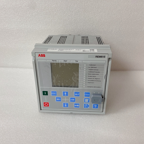
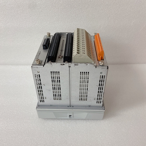
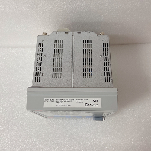
HBMBCAAJABC1BNN11G操作显示器
电压调节器电路:电压调节器感应发电机
电压,比较矩形 ed参考电压的样本
电压,并提供 维持
发电机电压与参考电压之间的预定比率
电压变压器T1是标准中的传感变压器
单相感应KCR 760电压调节器
设计用于三相感应的电压调节器包括两个:
感测变压器(T1和T3)。感测电路还包括:
变压器(T2)和电位计(R4)。变压器T2,电位计
R4和外部电流互感器提供了实现并联发电机运行期间的无功kVA负载分担。这个并联运行部件不影响电压调节器的运行当发电机单独运行时。
在配备欠频限制(UFL)或V/Hz选项的调节器上,该电路与调节器、传感和误差检测器相互作用
在低速运行期间降低电压的方式。固态 每次发电机启动时,灰化电路工作。这个 灰化
当发电机电压达到约70%时,电路断电额定电压输出。大多数电路都包含在印刷电路板上电路板。
单独安装在调节器上的部件
情况是感测变压器、并联操作变压器T2,扼流圈L1,标称电压范围设置为调整R2,稳定性调整R6,电容器C32、C33和C34、并联电压降电位器R4,功率级和保险丝。外部电压调节变阻器VAR为用于安装在控制面板上。单台发电机运行期间的感应电路:电压感应变压器提供与发电机电压成比例的电压输出该电压通过T2的初级绕组馈送至全波直肠 er由硅二极管D3、D4、D17、D18、D23和D24组成 ed电压为 由电阻器R3、扼流圈L1和电容器滤波Cl.来自 lter应用于错误检测器低频限值。
通过以下方式使二次并联运行变压器T2短路:使用跨接杆跨接CT和CT1,或将R4旋转至最大
逆时针位置或将装置/并联开关设置为单元,消除了单台发电机运行期间T2的影响。并联发电机无功运行期间的感应电路电压降补偿模式:发电机互联无功电压降补偿将按比例共享电感并联运行期间的无功负载,发电机减少系统电压。中描述了这种kVAR负载分担方法以下段落。
传感变压器提供的电压与感测电压。一个电流互感器(CT),安装在第二条线路上:发生器产生与振幅成比例的信号,并且与线路电流的相位。该信号在滑线并联电压降调整电位计R4。设置
R4确定该电压的多少施加到初级电源变压器T2。
Voltage regulator circuits: The voltage regulator senses the generator
voltage, compares a recti ed sample of that voltage with a reference
voltage, and supplies the eld current required to maintain the
predetermined ratio between the generator voltage and the reference
voltage. Transformer T1 is the sensing transformer in a standard
single-phase sensing KCR 760 voltage regulator while a KCR 760
voltage regulator designed for three-phase sensing includes two
sensing transformers (T1 and T3). The sensing circuitry also includes a
transformer (T2) and potentiometer (R4). Transformer T2, potentiometer
R4, and an external current transformer provide means of attaining
reactive kVA load sharing during parallel generator operation. The
parallel operation components do not affect voltage regulator operation
when the generator is operated singly.
On regulators equipped with underfrequency limit (UFL) or V/Hz option,
this circuitry interacts with the regulator sensing and error detector in a
manner that decreases voltage during underspeed operation. A solid-state
ashing circuit operates each time the generator is started. The ashing
circuit de-energizes when generator voltage has built up to about 70%
of rated voltage output. Most of the circuits are contained on a printed
circuit board. Parts that are individually mounted on the regulator
case are the sensing transformer(s), parallel operation transformer T2,
choke L1, nominal voltage range set adjust R2, stability adjustment R6,
capacitors C32, C33, & C34, parallel voltage droop potentiometer R4,
the power stage, and a fuse. External voltage adjust rheostat VAR is
provided for installation on a control panel.
Sensing circuit during single generator operation: The voltage sensing
transformer(s) provides a voltage proportional to the generator voltage
output. This voltage is fed across the primary of T2 to a full-wave
recti er comprised of silicon diodes D3, D4, D17, D18, D23, and D24. The recti ed voltage is ltered by resistor R3, choke L1, and capacitor
Cl. The dc signal from the lter is applied to the error detector and the
underfrequency limit.
Shorting the secondary parallel operation transformer T2, either by
using the jumper bar across CT and CT1, or turning R4 to its full
counterclockwise position or setting the UNIT/PARALLEL switch to
UNIT, eliminates the effect of T2 during single generator operation.Sensing circuit during parallel generator operation in reactive
voltage droop compensation mode: Generators interconnected for
reactive voltage droop compensation will proportionally share inductive
reactive loads during parallel operation by a decrease in generator
system voltage. This method of kVAR load sharing is described in the
paragraphs that follow.
The sensing transformer(s) provides a voltage proportional to the
sensing voltage. A current transformer (CT) installed in line two of
the generator develops a signal that is proportional in amplitude and
phase to the line current. This signal develops a voltage across the
slide-wire parallel voltage droop adjust potentiometer R4. The setting
R4 determines how much of this voltage is applied to the primary
transformer T2.

