


")
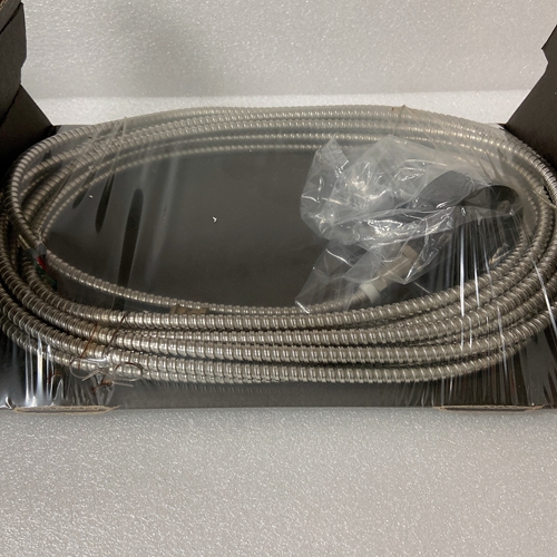
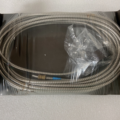
PR9268/202-100前置传感器
伺服星以正交编码器的形式向您提供电机位置输出
信号消除了对附加位置反馈装置的需要。产出如下:差分线路驱动器。有一个相关的直流公共输出(C4:引脚3),可以连接将共模噪声和电压峰值降至最低,以保护设备。由于控制器和驱动器之间通常存在电位差,建议连接(如果出现接地回路,断开并重新测试)。
编码器等效输出(EEO)信号的来源取决于电机类型
反馈装置:本节从固件版本开始介绍各种反馈类型及其功能0.1.8.增量编码器
输出信号是实际编码器反馈信号,在驱动器的电机参数。它可以按2的倍数缩小(编码:1、2、4、8、16)并且具有3MHz的最大频率限制。
伺服星可以使用编码器反馈来监控电机轴位置。相反旋转变压器是绝对位置反馈装置,编码器是增量装置
其指示位置的变化。伺服星的编码器分辨率(因此驱动器的编码器等效输出)是固定的,因为它是
编码器装置。
编码器接口包括三组导线
1.A/B(和补码)线构成编码器正交信号。信号是:在通过断线之前通过线路接收器差分接收检测电路。
2.窄指数脉冲通常每转出现一次,表示已知轴的物理位置。该脉冲通过线路接收器差分接收然后通过断线检测电路。该信号是硬件可接受的。3.门厅信号提供表示
电机轴。根据该信息,电机可以正弦换向,直到检测到索引信号-此时,真实位置已知。这些信号是:
由光耦合器隔离,并且可以是差分或开路集电极型信号。当使用伺服星作为编码器源时,推荐的电缆长度不再是超过50英尺(15米)。长编码器电缆往往具有较高的直流电阻,可能会产生:编码器供电线路中的显著负载效应。请仔细考虑这一点设计系统。允许使用更长长度的选项实现了位于电机处的独立电源,为编码器提供电源。返回到的正交信号驱动器是差分连接的,这通常不会构成较长电缆的问题长度。
分辨率和精度基于伺服星编码器的系统通常显示出最小的误差编码器本身。要获得大致的总价值,客户只需查看所用编码器的规格。
The SERVOSTAR provides a motor position output to you in the form of quadrature encoder
signals eliminating the need for an additional position feedback device. The outputs are
differential line drivers. There is an associated DC common output (C4: pin 3) which can connect
to your port to keep common mode noise and voltage spikes minimized for device protection.
Because there are normally differences of potential between your controller and the drive,
connection is recommended (if ground loops occur, disconnect and retest).
The source of the Encoder Equivalent Output (EEO) signals depends on the type of motor
feedback device:
This section describes the various feedback types and how they function beginning with firmware version
0.1.8. Incremental Encoder
The output signal is the actual encoder feedback signal that is pre-configured (MENCRES) in the
drive’s motor parameters. It can be scaled down by multiples of two (ENCOUTO: 1, 2, 4, 8, 16)
and has a maximum frequency limit of 3 MHz.
The SERVOSTAR can use encoder feedback to monitor the motor shaft position. As opposed to
a resolver, which is an absolute position feedback device, the encoder is an incremental device
that indicates changes in position. The encoder resolution of the SERVOSTAR (and therefore
the drive’s encoder equivalent output) is fixed because it is a hardware characteristic of the
encoder device. The encoder interface includes three groups of wires:
1. A/B (and complements) lines make up the encoder quadrature signals. The signals are
received differentially through line receivers before being passed through a wire-break
detection circuit.
2. The narrow Index pulse normally appears once per revolution and indicates a known
physical position of the shaft. This pulse is received differentially through a line receiver
before being passed through a wire-break detection circuit. This signal is hardwarecapturable.
3. Hall signals provide information representing the approximate absolute location of the
motor shaft. From this information, the motor can sinusoidally commutate forward until
the index signal is detected - at which time, true position is known. These signals are
isolated by an opto-coupler and can be differential or open-collector type signals. The recommended cable length when using the SERVOSTAR to source the encoder is no longer
than 50 ft. (15 m). Long encoder cables tend to have high DC resistance that may create
significant loading effects in the supply lines to the encoder. Please consider this carefully when
designing the system. An option that would allow the use of longer lengths, implements a
separate supply located at the motor to source the encoder. Quadrature signals returned to the
drive are differentially connected which normally do not constitute a problem with longer cable
lengths.
Resolution and Accuracy
A SERVOSTAR encoder-based system typically exhibits minimal inaccuracies outside of the
encoder itself. To get an approximate total value the customer need only look to the
specifications listed for the encoder being used.

