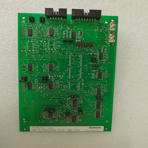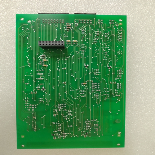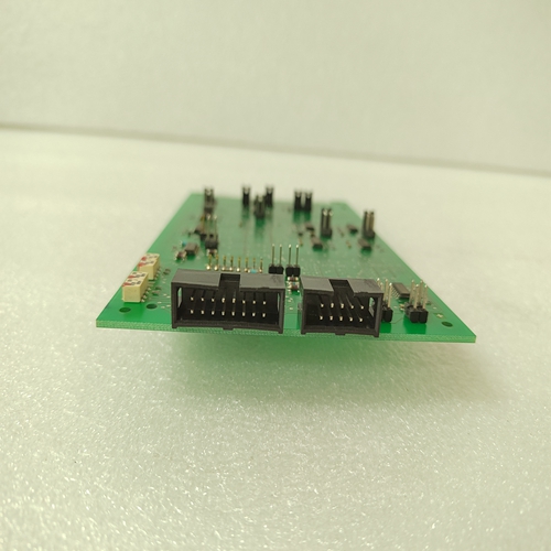
VT-MVTW-1-16/D伺服驱动模块
控制主接触器(K1)的接通和断开通过数字输出DO5。在紧急情况下关闭主接触器由紧急断开控制按钮,可随时关闭。负载下
主接触器产生火花的条件当火花发生时产生高电压出来为保护转换器免受高压a压敏电阻MOV S20K625需要与直流并联接线盒C1/D1。
在所有紧急情况下,驱动器故障跳闸
因为电枢电路开路。概述本手册旨在帮助以下人员:
晶闸管功率转换器的规划、安装、启动和维护。
这些人应具备:•物理和电气工程、电气布线原理和组件的基本知识
电气工程中使用的符号,以及•直流驱动器和产品的基本经验。
操作面板DCS 400 PAN
控制和显示面板用于参数设置,用于反馈值测量和驱动采用DCS 400系列晶闸管功率转换器进行控制。
面板链接
DCS 400 PAN通过串行接口,在通电时可拆卸。初始化
接通电子电源后,面板显示:立即获取实际值。
输出显示面板显示最多可显示四个实际值
第一行有三个值,第二行有一个值
线对于单个显示器,可以安排:通过参数面板Act 1…4以任何顺序显示。如果面板状态行中显示输出显示,按0(18)键切换到菜单
选择菜单选择模式允许您:访问参数组和函数
可获得的按下0(18)键后,将始终显示菜单项1电机设置。
使用这些键,上面显示的列表可以滚动不停。
为了有效地选择所显示的特定菜单项,按下(17)确认选择(5.显示然后将切换到所选菜单项。前九个菜单项或参数组为:用于设置驱动参数。
要访问所需的参数组,请选择使用滚动功能的相关组,以及按下(17(5)进行确认。显示器现在切换到参数选择级别。要访问此组中的参数,请选择并确认该参数
如上述参数所述组的编号、名称和带下划线的值此时显示所选参数。
Switch Main Contactor (K1) On and Off is controlled
by digital output DO5. In case of Emergency Off the
Main Contactor is controlled by the Emergency Off
button and can switched off at any time. Under load
condition that produce sparking on Main Contactor
which produce high voltage when the sparking goes
out. To protect the converter against high voltage a
Varistor MOV S20K625 is needed in parallel to the DC
terminal block C1 / D1.
In all cases of Emergency Off the drive trips with fault
because the armature circuit is open.General
This manual is designed to help those responsible for
planning, installing, start-up and servicing the thyristor power converter.
These people should possess:
• basic knowledge of physics and electrical engineering, electrical wiring principles, components
and symbols used in electrical engineering, and
• basic experience with DC drives and products.
Operating panel DCS 400 PAN
The Control and Display Panel is used for parameter
setting, for feedback value measuring and for drive
control with series DCS 400 thyristor power converters.
Panel link
The DCS 400 PAN is connected to the drive via a
serial interface and is removable under power.
Initialization
After switch on electronics supply the panel shows
actual values immediately.
OUPUT display
The panel display can show up to four actual values.
Three values at the first line and one at the second
line. For individual display it is possible to arrange
these in any order via Parameter Panel Act 1…4 .If OUTPUT is indicated in the status line of the panel
display, press the 0(18 key to change over to menu
selection. The menu selection mode allows you to
access the parameter groups as well as the functions
available.
After pressing the 0(18 key, menu item 1 Motor Settings will always be displayed.
Using the keys, the list shown above can be
scrolled endlessly.
To effectively select a specific menu item displayed,
confirm the selection by pressing (17(5 . The display
will then switch to the menu item selected.The first nine menu items or parameter groups are
used for setting the drive parameters.
To access the desired parameter group, select the
group concerned using the scrolling functions and
confirm by pressing (17(5 . The display now switches
to the parameter selection level. To access a parameter from this group, select and confirm the parameter
concerned as described above for the parameter
group. The number, name and underlined value of the
parameter selected is now displayed.


