


")
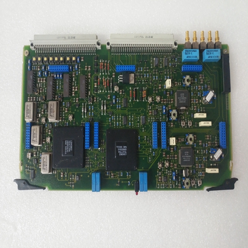
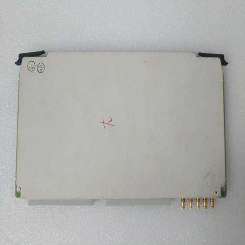
033.733.002机器人模块卡件
伺服驱动模块及其电源模块均为齐平安装设备,如DIN VDE 0160第5.5.1.3节和第6.5.2.3节所述。
这意味着它们用于安装在控制柜中。知识产权10是它们的保护类别。
控制柜外壳应符合以下安全要求:适用于此应用的指南,保证充分的保护
防止一般公众可进入的区域发生危险。(用于工业应用,例如,参见EN 60204/DIN VDE 0113第1节。)
只有经过适当培训并拥有适当工具或钥匙的人员才能:进入控制柜内部。
如有可能,模块化装置应按图所示进行布置34.高功率和高电压的驱动器应尽可能靠近尽可能地提供给供应单元。如果通风伺服驱动模块TDM3和TDM 4(型号名称TDM 3.2-030-300-W1或TDM 4.1-030-300-W11)或TDM 6和TDM 7(型号名称TDM 6.1-025-300-W1或TDM 7.1-025-300-W1)
–布置在驱动包的左侧,–安装在左侧
距离相邻模块,然后必须拧上冷却挡板(INDRAMAT垫编号224 869
安装在装置左侧的散热器上。(另请参见尺寸伺服驱动模块表。)只有这种安排才能保证:风扇将提供足够的冷却。电源模块附件组中的端塞为插入装置中距离最远的接触条X1电源模块。
它监视线路连接X1。也可以将带有电源模块的驱动模块布置在右对齐左侧的驱动模块。图35至图40显示了单个伺服驱动器的前视图带电气连接附件的模块和编程模块模块模块。电气连接所需的部件是“电气连接附件”由INDRAMAT提供。
Both the servo drive module and its supply module are flush mounting
equipment, as outlined in DIN VDE 0160, Sections 5.5.1.3 and 6.5.1.3.
This means that they are intended for mounting in a control cabinet. IP
10 is their protection category.
The control cabinet housing should, in accordance with those safety
guidelines valid for this application, guarantee sufficient protection
against hazards in areas where the general public has access. (For
industrial applications, e.g, see EN 60204/DIN VDE 0113, Section 1.)
Only properly trained personnel with proper tools or keys should have
access to the interior of the control cabinet.
The modular units should, if possible, be arranged as depicted in Figure
34. The drives with high power and voltages should be located as close
as possible to the supply unit.
If the ventilated servo drive modules TDM3 and TDM 4 (type designation
TDM 3.2-030-300-W1, or TDM 4.1-030-300-W1) or TDM 6 and TDM 7
(type designation TDM 6.1-025-300-W1, or TDM 7.1-025-300-W1)
– are arranged on the left side of the drive packet, or,
– are mounted on the left side at a distance greater than 10 mm from an
adjacent module,
then a cooling baffle (INDRAMAT mat. no. 224 869) must be screwed
onto the heatsink on the left side of the unit. (Also see the dimensions
sheet for the servo-drive module.) Only this arrangement guarantees
that the fan will provide sufficient cooling.
The end plug, found in the accessories set of the supply module, is
plugged into contact strip X1 located in the unit farthest away from the
supply module.
It monitors the line connection X1.
It is also possible to arrange the drive module with supply modules on the
right and line up the drive modules on the left.Figures 35 through 40 depict a front view of the individual servo drive
modules with electrical connecting accessories and programming module MOD.
The components needed for the electrical connections are a part of the
„electrical connecting accessories“ supplied by INDRAMAT.

