


")
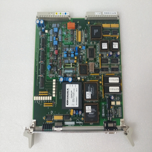
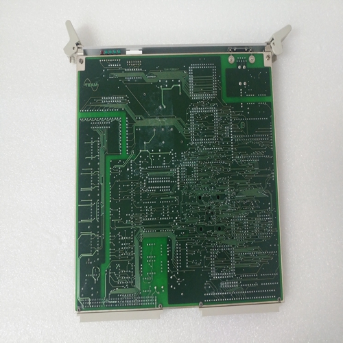
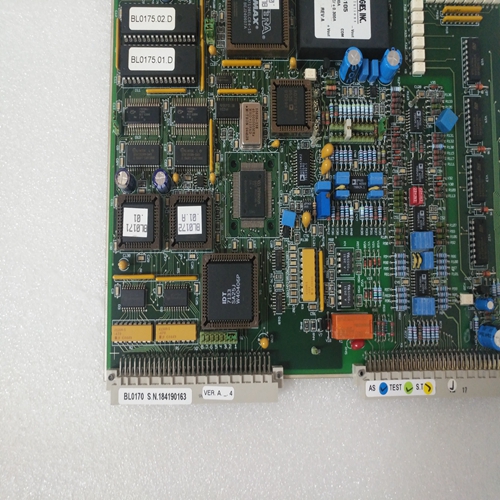
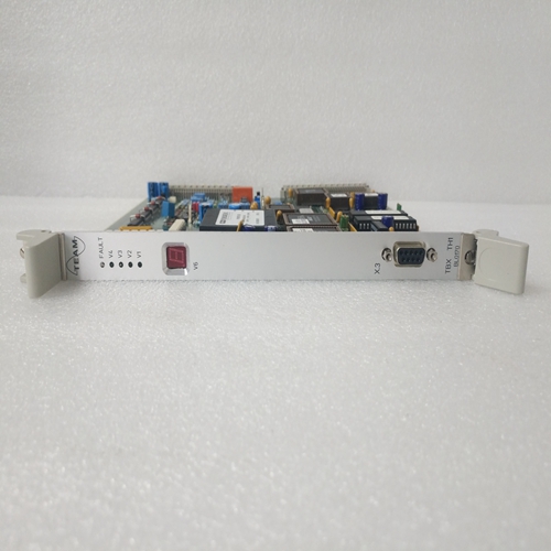
TEAM BL0170模块
电源电压施加后,驱动放大器发出信号
当它们“准备就绪”时,伺服驱动器可以通过以下方式以受控速度运行:–在射频输入端注入控制器启用信号,以及–施加与电机成比例的模拟设定点电压速度,跨输入
•E1和E2或•E3和0虚拟机或•E4和0虚拟机。
可以进行以下设置:(参见图8中的伺服驱动模块)。
输入E1-E2是差分输入,输入E3和E4是求和输入它们被称为0 VM。
速度加权(输入灵敏度)已在中设置MOD编程模块上的工厂。提供了两种设施:电阻器和电位计值并入MOD根据所需的输入权重对模块进行编程使用者
编程模块类型名称的最后三位数字指定:输入加权(见第3.2节)。
如果没有可用的用户数据,则MOD编程模块将给出
每最大速度值10伏的输入加权(无调整电位计)。
NC输出的速度设定点可以平滑,如果楼梯功能明显受到干扰。应该注意的是,过度平滑可以降低位置控制的动态响应,并且从而减慢反应时间。
设定点平滑只能通过使用微分来实现输入E1-E2。通过将电容器C5焊接到
MOD编程模块(最大可达3uF,对应于大约5至7ms的平滑时间常数)。
当电机顺时针旋转时,从输出轴看旋转方向如下:差分输入E1-E2:E1处的电压为正关于E2
对输入E3、E4求和:E3或E4处的电压为负关于0VM
T处的转速计测量信号(感测):电压相对于对于0VM,如果另一个旋转方向是:
渴望的:–在差分输入E1-E2处交换连接,如果使用,–通过连接端子X6/9和X6/10,反转所有输入的方向在控制放大器处。通过互换电机连接来反转旋转方向
这是不可能的,并导致驱动器故障。速度控制器具有极低的温度漂移。零可以在底部的“调零”电位计上校正漂移前面板右侧(第5.2.2节图35至40中的前视图)。应始终在初始操作和更换后检查漂移
伺服驱动模块:如果轴以零速度设定点移动,则轴的旋转运动应通过上的“调零”电位计设置为零控制柜达到最终温度时的前面板。
After the mains voltage has been applied and the drive amplifiers signal
that they are „ready“, the servo drive can be run at controlled speed by
– injecting the controller enabling signal at the RF input and
– applying an analogue set-point voltage, that is proportional to the motor
speed, across the inputs
• E1 and E2 or
• E3 and 0 VM or
• E4 and 0 VM.
The following settings are possible: (see basic circuit diagram of the
servo drive module in Fig. 8).
Input E1-E2 is a differential input, inputs E3 and E4 are summing inputs
that are referred to 0 VM.
The speed weighting (input sensitivity) has already been set in the
factory on the MOD programming module. Two facilities are provided The resistor and potentiometer values are incorporated into the MOD
programming module according to the input weighting required by the
user.
The last three digits of the programming module type designation specify
the input weighting (see Section 3.2).
If no user data are available, the MOD programming module is given the
input weighting of 10 volts per max. speed value (no adjustment
potentiometer).The speed set-point output by the NC can be smoothed if the staircase
function becomes noticeably disturbed. It should be noted that excessive
smoothing can reduce the dynamic response of the position control and
thus slow the reaction time.
Set-point smoothing can be implemented only by using the differential
input E1-E2. Smoothing is provided by soldering a capacitor C5 onto the
MOD programming module (up to a maximum of 3uF is possible,
corresponding to a smoothing time-constant of approximately 5 to 7 ms).
With the motor rotating clockwise, as viewed from the output shaft, the
direction of rotation is as follows:
Differential input E1-E2: voltage at E1 is positive
with respect to E2
Summing inputs E3, E4: voltage at E3 or E4 is negative
with respect to 0VM
Tacho measuring signal at T(sense): voltage is positive with respect
to 0VM The following facilities are provided if another direction of rotation is
desired:
– Interchange the connections at differential input E1-E2, if this is used,
– Reverse the direction of all inputs by linking terminals X6/9 and X6/10
at the control amplifier.
Reversing the direction of rotation by interchanging motor connections
is not possible and causes the drive to malfunction.
The speed controller has an extremely low temperature drift. The zero
drift can be corrected on the „ZERO ADJ“ potentiometer at the bottom
right of the front panel (front view in Figs. 35 to 40 in Section 5.2.2).
The drift should always be checked at initial operation and after replacing
the servo drive module:
If the axis moves with a zero speed set-point, the rotary motion of the axis
should be set to zero by means of the „ZERO ADJ“ potentiometer on the
front panel when the control cabinet has reached its final temperature.

