


")
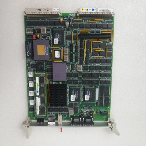
TEAM BG0090系统卡件
电源模块从产生直流链路电路电压交流输入电压。由此,伺服驱动模块生成三相系统,该三相系统根据振幅、频率和阶段根据电流,这适用于MAC伺服电机转子位置和所需速度。
受控三相系统与伺服电机的受控运行状态根据
符合以下标准:扭矩:伺服系统定子中三相系统的电流幅值
电机通过永磁励磁转子的磁场确定产生的转矩。这是由于系统速度偏差造成的控制器。
速度:三相系统的频率决定了伺服电机。转子的位置和频率由转子位置编码器的信号(BLC信号),取决于所需的磁场位置与转子和定子电流的位置。扭矩方向:三相系统和转子磁场之间的相位关系决定了转矩的方向
导出根据速度控制器的系统偏差的极性。
控制电路信号调节:速度控制器将速度设定值与实际值进行比较从中生成电流设定点,并将其馈送至方向电流控制器(参见图5)。
根据转子位置(通过BLC信号从转子位置编码器),三个定子的电流方向对绕组进行控制,使定子中产生的电流处于其相对于转子的磁通量是最有利的。这该关系确保扭矩与电机电流成比例。
电机电流由电流控制器控制。这与方向电流控制器,以控制三个以便获得具有受控幅度、频率和相位的三相系统。电流控制器的输出信号在脉冲宽度内定时并经由无电势驱动器级放大。这个用于驱动三相电桥的放大信号来自六个功率晶体管。MAC三相伺服电机是永久励磁同步电机,由以下主要子组件组成:–三相定子–永久励磁转子–可选电动释放制动器–可选单独轴流风机,用于表面通风
The power supply module generates the DC link circuit voltage from the
AC input voltage. From this the servo drive module generates a threephase system that is controlled according to amplitude, frequency and
phase. This is applied to the MAC servo motor according to the current
rotor position and the desired speed.
The relationship between the controlled three-phase system and the
controlled operating states of the servo motor is established according
to the following criteria:
Torque:
The current amplitude of the three-phase system in the stator of the servo
motor determines the resulting torque via the field of the permanentmagnet-excited rotor. It results from the system deviation of the speed
controller.
Speed:
The frequency of the three-phase system determines the speed of the
servo motor. The rotor’s position and frequency is derived from the
signals of the rotor position encoder (BLC signals), depending on the
required synchronism between the position of the magnetic field of the
rotor and the position of the stator current.Direction of torque:
The phase relationship between the three-phase system and the magnetic field of the rotor determines the direction of the torque and is derived
from the polarity of the system deviation of the speed controller.
Control circuit signal conditioning:
The speed controller compares the speed set-point and actual-value and
from them generates the current set-point that is fed to the directional
current controller via a limiter circuit (see Fig. 5).
Depending on the rotor position (signalled via the BLC signals from the
rotor position encoder), the direction of the current for the three stator
windings is controlled so that the resulting current flow in the stator is at
its most favourable in relation to the magnetic flux of the rotor. This
relationship ensures that the torque is proportional to the motor current.
The motor current is controlled by a current controller. This is linked to the
directional current controller in order to control the current in the three
phases so as to obtain a three-phase system having controlled amplitude, frequency and phase.
The output signals of the current controller are timed in the pulse-width
modulation stage and amplified via potential-free driver stages. The
amplified signals used for driving the three-phase bridge constructed
from six power transistors.The MAC three-phase servo motor is a permanently-excited synchronous motor that is made up of the following main sub-assemblies:
– three-phase stator
– permanently-excited rotor
– optional electrically-released brake
– optional separate axial fan for surface ventilation

