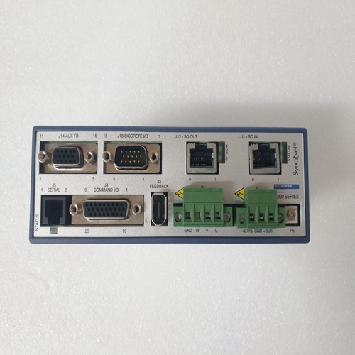
KOLLMORGEN S20330-SRS驱动器模块
模拟输入模块
图2-5中框图的第一部分显示了用于处理32模拟输入。现场输入连接在测距电阻器上,该电阻器在中选择
根据要处理的场输入类型(电流或电压)。信道信号然后沿四条路径(A至D)分布;路径A、B和C是三重信号处理电路和路径D为计量测试点供电。
在每个路径中,信号首先通过RF和低通滤波器,然后再应用到32信道多路复用器的一个信道。对于路径A、B和C,来自公共接口中的微控制器被隔离、解码并用于选择输入信道将切换到多路复用器的输出。然后缓冲多路复用器输出并发送到模数(ADC)转换器,该转换器产生编码的串行数据输出
以表示信道输入信号的幅度。连接到ADC的工厂设置链路使基本模块能够配置为不同的+5Vdc或+10Vdc电压范围。
这个ADC输出通过光隔离器传输到公共接口进行处理。
路径D中没有ADC,缓冲信号直接施加到测量测试点前面板。通过相邻的信道选择器开关进行信道选择。
模块的电源为5.4Vdc和12Vdc,由每个双冗余SC300E提供电源装置。每条线路分为四个分支,为每个四条路径。每个支路中两个电源(12V和5.4V)的双输入均通过“或”进行二极管提供双重冗余。在滤波和浪涌限制之后,输出轨道转向*(标称12V)和VCC*(标称5V)向它们各自的路径提供功率。A、B和C 5V轨道还向公共接口中的相应控制电路供电。
每个A、B和C路径电源也被连续监控,并且监控输出A/PSOK、B/PSOK和C/PSOK通过公共接口发送到MPPs用于诊断目的。
前面板上的在线/离线请求开关可将请求发送至MPPs为了维护目的,将模块离线。
该模块包含一个硬件识别电路,用于系统识别单元链接
只有用户可更改的链接被标识为LK3,位于的右上角模块(见图1-1)。链路(LK3)使模块能够设置为321或320模式。
Analogue input module The first part of the block diagram in Figure 2-5 shows the circuit used to process one of the 32 analogue inputs. The field input is connected across a ranging resistor which is selected in accordance with the type of field input to be processed (current or voltage). The channel signal is then distributed along four paths (A to D); paths A, B and C are the triplicated signal processing circuit and path D feeds the metering test point. In each path the signal is first passed through RF and low-pass filters before being applied to one channel of a 32 channel multiplexer. For paths A, B and C a command from the microcontroller in the Common Interface is isolated, decoded and used to select which input channel will be switched to the output of the multiplexer. The multiplexer output is then buffered and sent to an analogue to digital (ADC) converter which produces a serial data output coded to represent the amplitude of the channel input signal. Factory set links connected to the ADC enable the basic module to be configured for different +5Vdc or +10Vdc voltage ranges. The ADC output is passed via an opto-isolator to the Common Interface for processing. There is no ADC in path D, the buffered signal is applied directly to the metering test point on the front panel. Channel selection is by means of the adjacent channel selector switches. Power to the module is 5.4Vdc and 12Vdc supplied by each of the dual redundant SC300E power supply units. Each line is divided into four branches to provide a supply to each of the four paths. The dual inputs for both supplies (12V and 5.4V) in each branch are ORed via diodes to provide the dual redundancy. After filtering and surge limitation the output rails VEE* (nominally12V) and VCC* (nominally 5V) provide power to their respective paths. The A, B and C 5V rails also supply power to the corresponding control circuits in the Common Interface. Each of the A, B and C path supplies is also continuously monitored and the monitor outputs A/PSUOK, B/PSUOK and C/PSUOK are sent via the Common Interface to the MPPs for diagnostic purposes. An On/off Line Request switch on the front panel enables a request to be sent to the MPPs that the module be taken off-line for maintenance purposes. The module contains a hardware identity circuit that enables system identification of the module. Links Only user changeable link is identified as LK3 and located in the top right hand corner of the module (see Figure 1-1). The link (LK3) enables the module to be set for 321 or 320 mode.


